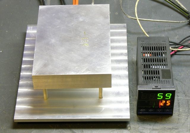
Keith of Keith’s Electronics Blog made a PID-Controlled Soldering Hotplate based on the one I fabricated earlier this year. He’s already using it to build the stepper controller PCB for the MakerBot CupCake CNC!
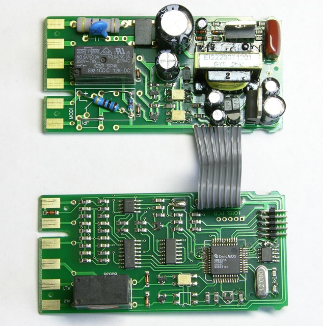
He also posted a bunch of teardown photos (like the one shown below) of the CD101 PID Controller from Sure Electronics. I suspect the CD101 is a cheap knockoff of an RKC PID controller since I can’t find the part number on RKC’s website, even though the front panel clearly says RKC on it. I guess at $40 you can’t ask too many questions, the price is right…
Copycat PID-Controlled Solder Hotplate « Keith’s Electronics Blog.


Keith,
Thanks for all this. I’ve just spent the last 24 hours trying to wrestle with getting a (Canadian import) CD101 working here in the UK.
Your post was incredibly helpful in identifying the differences between the CD101 as supplied in North American for controlling SSD relays, and those supplied my side of the Atlantic 🙂
A few things I’ve learnt:
– the difference we have between 230v/50hz vs. 110v/60hz doesn’t matter. The CD101 copes. (This is the only good news!)
– there are many, many subvariants of the CD101 – I think that the teardown in the post is for a “V” version (12v output for controlling SSD relay) rather than the “Relay” version (such as I have.)
– for the relay version, ignore the various blog posts on the internet – instead take a 12v power supply, and create a circuit – 12v+ -> CD101 Pin 4 -> Relay control + -> Relay control – -> CD101 Pin 5…. and THAT my paduan, actually works 🙂
– ignore anything the circuit diagram tells you about NO/NC relay pinouts. I had to teardown the CD 101-Relay version, find the internal relay fitted, and from that thing’s datasheet, discover that the NO (normally open) version of that relay was NOT FITTED (despite what the circuit diagram in the CD101 manual and on-board sticker said!) and the relay was an SPST 🙁
– (AND THIS IS IMPORTANT!) – Ignore what your multimeter tells you about what the pin4 pin 5 CD101 output relay is doing. THIS OUTPUT ONLY WORKS UNDER LOAD! And the multimeter simply doesn’t register it connecting on OUT1 HIGH, until you have (at least) a 12v load across it (which I used to power an electromechanical relay, controlling a 230v heating load.)
Anyway, thank you again! I now have a working sous vide machine, and your teardown was a vital resource in getting it working in spotting the differences 🙂
Mark in Sussex, England
Missing note:
The that read:
– for the relay version, ignore the various blog posts on the internet – instead take a 12v power supply, and create a circuit – 12v+ -> CD101 Pin 4 -> Relay control + -> Relay control – -> CD101 Pin 5…. and THAT my paduan, actually works
Should have said:
– for the relay version, ignore the various blog posts on the internet – instead take a 12v power supply, and create a circuit – 12v+ -> CD101 Pin 4 -> Relay control + -> Relay control – -> CD101 Pin 5 [MISSING] -> 12v-[/MISSING]…. and THAT my paduan, actually works
I would like to know what sort of clearance hole was necessary for the heater in the hotplate. I saw the spec diameter of the heater was 1/2 inch. Will the thermal expansion of the heater itself cause any problems or does the plate expansion compensate for that of the heater?
What would be the consequences of increasing the plate size to 4″ X 6″ be. Will the heater have enough oomph to handle the increase in the thermal mass?
Any enlightenment will be appreciated.
Vic
Victor,
Very good question, because this is something that is pretty critical in making a hotplate that works well and doesn’t damage the cartridge heater.
The basic rule is that the hole for the heater should be drilled to the stated diameter of the heater. Ie. a 1/2″ heater requires a nominally 1/2″ hole. It turns out that heaters are manufactured slightly undersize to allow for this – a 1/2″ heater is actually 0.492-0.497″ in diameter. This allows a slip fit into the hole while still providing good thermal contact when the heater expands as it warms up.
In general this works, but in certain situations you may need to actually do the math to find the optimum hole size for a given heater. Omega.com has a good article explaining how hole size (fit) corresponds with allowable watt density of the heater for a given operating temperature. The graph here allows you to pick a hole size based on your other requirements, or vice versa. I think generally a 0.10-0.15″ hole ID – heater OD is recommended.
The choice of wattage depends on a lot of things, such as size of the hotplate, desired operating temperature, tradeoff of warmup time vs. overshoot, thermal losses due to standoffs, air convection, etc. I used 500W for my plate because it’s a common power rating for 110V 1/2″x4″ cartridge heaters. It was mostly a guess, perhaps also guided by the specs of some commercial hotplates I saw. I was prepared to buy a different heater if 500W wasn’t right – fortunately they are fairly cheap and easy to swap out!
If you don’t have very good control over the finished size of the hole or if you just want a more conservative design, I would recommend avoiding the highest wattage spec for a given size of heater. Ie. if a 1/2″ diameter 3″ long cartridge heater is available in 250, 500, and 750W, I would avoid 750W as the highest watt density requires the closest hole fit to avoid damaging the heater.
Hope this helps!
Jeff
PS: If you haven’t seen it, my heater is very similar to Keith’s shown above.
Jeff,
Thanks for taking the time to answer my questions. Just the info I needed.
Regards
Vic
I’m trying to figure out how to create a custom sized hot plate for my encaustic work. The wax needs to be kept below 200 degrees, would something like this set up for for me?
Thank you!
Shelly – I don’t see why not. Assuming you mean 200 degrees Fahrenheit, you could probably get by with a lower wattage heater unless your hot plate is huge. The PID controllers will accept any temperature, so you would just dial it in for 200F instead of 400.
Keith – Thank you very much for taking the time to include proper attribution, most people don’t. As long as my name and a link to the original page is in there somewhere I am happy!
I think you are only the second person to make a hotplate based on mine. It’s great to see the other designs – in the end I’ll probably incorporate the improvements everyone else makes to make mine even better. 🙂
Thanks!
Jeff
Jeff, welcome back from your cross-country trip!
I hope I gave you appropriate and adequate attribution in my blog post. I was pleased to see that the Make: blog entry included my first paragraph that linked to your original project — so hopefully you got some hits off the publicity too.
Let me know if there’s anything you feel was attributed inappropriately or inadequately and I’ll do my best to make amends. And thanks again for the idea and all the input!