Category Archives: Projects

Building a Wifi Radio – Part 1, Introduction

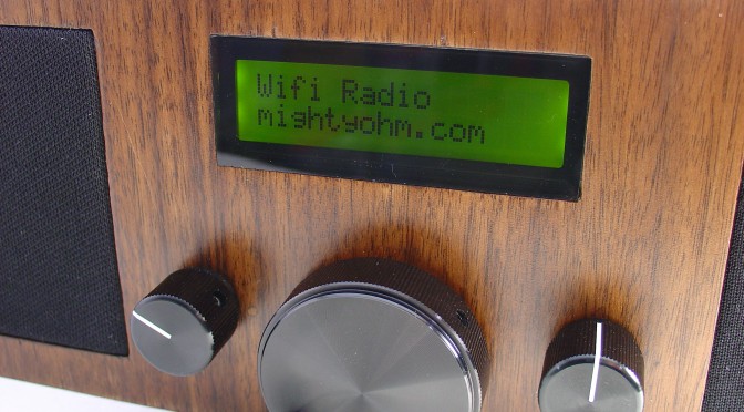
This article is the first of a series that will document the development of a low cost, open source wireless streaming internet radio receiver.  All construction details, including schematics, source code, and even the design process itself will be documented on this blog.

Comments and (constructive) criticism are welcome. Click here to post a comment.

Table of Contents:

  1. Building a Wifi Radio – Part 1, Introduction (you are here)
  2. Building a Wifi Radio – Part 2, Choosing an Embedded Platform
  3. Building a Wifi Radio – Part 3, Hacking the Asus WL-520GU
  4. Building a Wifi Radio – Part 4, Installing OpenWrt
  5. Building a Wifi Radio – Part 5, Let’s Make Some Noise!
  6. Building a Wifi Radio – Part 6, A Conversation with Mpd
  7. Building a Wifi Radio – Part 7, Building an LCD Display
  8. Building a Wifi Radio – Part 8, Adding a Tuning Control
  9. Building a Wifi Radio – Part 9, A Few Odds and Ends
  10. Building a Wifi Radio – Part 10, Building the Box

Some background:

According to Wikipedia, in 1993 the first internet radio program began distribution.  At that time, radio programs were manually downloaded to be played later on the user’s home computer; the user experience was far from that of listening to a traditional broadcast radio receiver.  It was not until several years later that streaming radio became common, giving birth to internet radio stations that could be listened to much like traditional radio, but with several advantages.  Most notably, internet radio stations were (and still are for the most part) largely devoid of on-air advertising, and stations anywhere on the globe could be received by anyone with access to the internet.  Over time, improvements in audio compression (such as MP3) and larger end user bandwidth improved the fidelity and reliability of internet radio.  The birth of common standards like Shoutcast made it possible to listen to many stations with a single player program, like Winamp.

Today, most music playback software supports streaming radio in some way.  iTunes features thousands of streaming radio stations and even supports Shoutcast streams so that users can easily add additional stations of their own.

The beautiful thing about streaming radio is the huge diversity in programming that is available.  Many college radio stations have a streaming server, like KDVSDigitally Imported hosts many electronic and dance music streams that give the listener the choice to listen to specific genres like ambient or gabber hardcore (whoa).  Broadcast radio usually lumps all electronic dance music into one category, much to the dismay of their listeners (who probably tuned out during the commercial break, anyway).  Gems like Slay Radio specialize in music you would never hear on broadcast FM, like Commodore 64 remixes.

In the past couple years, products have started to appear that mimic the form and function of a traditional radio, but play internet radio instead.  Good examples of these are the Roku SoundbridgeRadio and the ASUS Internet Air.  Remote speaker devices, such as the Apple Airport Express, require a PC to receive and relay streaming radio but achieve a similar end result (but don’t really look much like a radio).

The Wifi Radio project:

I have been wanting to build a streaming radio for some time.  I frequently work in my garage, where I occasionally use my Macbook to play music through a small amplifier and bookshelf speakers.  The problem is that my laptop is not always set up in the garage, and greasy fingers are not a good thing to have around a white laptop, period.  I could simply buy an internet radio, but I couldn’t stomach the $150-$300 price tag on most players for such a luxury.

So I decided to build one instead.

I started the design process by drafting an outline of desired features, and then breaking them down into wants and needs, while trying to keep the project scope under control.

Requirements:

  • Wireless connectivity through existing Wifi network
  • Audio output (preferably 44kHz, 16 bit stereo)
  • An integrated amplifier and speaker(s)
  • Shoutcast/MP3 streaming audio decode
  • Several builtin station presets
  • A display to indicate the station and currently playing song
  • Simple user interface, using standard radio controls (volume, tune, etc)
  • 110VAC operation

Optional features:

  • Line output (to connect to a receiver/amplifier)
  • Web server for configuration/management
  • Ability to play files off a USB stick or iTunes server

Definitely won’t be a feature:

  • Any kind of over-the-air radio tuner
  • Commercials
  • Pledge season
  • Morning DJ’s
  • “Blah, blah, blah.”

Now that we’ve defined the project…  it’s time for a commercial break.  That’s it for part 1 of this series.  Stay tuned for part 2, where I’ll talk about choosing an embedded platform for the design and why Linux is so awesome!

Update: Part two is now available, click here to see it!

Update 2: There is a new Wifi Radio Discussion Forum, hop over there to ask questions about the project or see what other people are working on!  (4/12/09)

Update 3 (6/1/09): I finally added a table of contents to the top of this post to help everyone (including me) navigate the series!

Old Dell + Debian Etch = Instant Development Server

Earlier this year I replaced my desktop PC, a Dell Dimension 4700, with a Mac Mini as part of my effort go 100% Mac for my home computing.  OS X is a terrific platform for the desktop power user because it looks great, feels great, is well supported by open source projects.  It also runs on a variant of Unix giving you full shell access and lots of other great stuff.

Since then, the Dell has been sitting by my desk, waiting for a good use.  I already have a Linkstation Live that I use for a low power home server (print server, mt-daapd, subversion, samba, etc.) so I didn’t have an immediate need for another PC around the house.

Last week I started playing with OpenWRT as part of a neat new project that will be an upcoming feature on this blog.  I suddenly needed a Linux environment and some extra computing power to help build custom OpenWRT images.  Debian to the rescue!

Before anyone says anything, I don’t really have anything against the incredibly popular desktop Linux distro Ubuntu.  The real reason I choose Debian is that I know Debian, and Debian just works.  My new server runs headless and I use ssh to login and compile from my Mac, so the advanced graphical features of Ubuntu would be lost on me.

Installing Debian is a breeze.  Within 30 minutes of burning the Debian quick start CD, I was up and running.  After installing a few addon packages, I was compiling OpenWRT images.

Instant development server.  Awesome.

Arduino-based AVR High Voltage Programmer

Arduino-based AVR High Voltage Programmer

Update 01/02/09: A PCB version of this circuit is in the design stages – some preliminary information is here.

Update 03/11/09: Kits based on this design are now for sale!

Update 12/14/10: The original AVR HV Rescue Shield kit has been replaced by the new and improved HV Rescue Shield 2.  Visit the HV Rescue Shield 2 product page for information about the new kit!

As I mentioned earlier this week, I recently “lost” an ATmega168 due to flashing the configuration fuses to disable the RESET pin, without realizing that this makes the device impossible to reflash with SPI.  This is particularly frustrating because the device is still 100% functional, just completely deaf to ordinary serial programmers.  The only way to recover the device is using what Atmel calls “High Voltage Parallel Programming Mode” which very few programmers support, most importantly, not the USBtinyISP I otherwise love.

Fortunately, my trusty Arduino came to the rescue – I created an Arduino-based AVR programmer that uses the high voltage programming mode and can fix pesky fuses like RSTDISBL.

The Arduino has just enough IO to implement the entire HV protocol plus a “go” button.  So far I have only implemented setting LFUSE and HFUSE in software, but there is no reason why the code couldn’t be extended to support chip erase and programming the entire flash as well.

Overview:

The fuse programming process is simple:

  • Upload the HVFuse sketch to the Arduino, available for download here: HVFuse.pde
  • Install the shield and apply +12VDC to the terminals on the left
  • Wait for the red LED to turn on (if it isn’t already)
  • Install the ATmega to be repaired
  • Push the button
  • As soon as the LED turns back on, the AVR is fixed and ready to be put back into service!

Schematic:

Here is an Eagle schematic of the HV Programming shield (click to enlarge):

Update 12/17/08:  An observant reader pointed out that there were three errors in the way GND/AGND, AREF and VCC/AVCC were connected on the target AVR in the original schematic.  The errors have been fixed and the updated schematic is below.  Apologies for any confusion this caused.

hvfuse_fixed.sch

Parts list:

  • An Arduino NG, Diecimila, or compatible
  • A piece of perfboard cut to size
  • Header pins for the Arduino interface (note I had to drill some of the holes to get the headers to fit the nonstandard pin spacing for digital lines 8-13.
  • An LED which indicates when it is ok to insert/remove the AVR
  • A 2N3903 or similar NPN transistor (2N2222, etc.)
  • (20) 1k resistors – these protect the Arduino from short circuits in case something goes wrong
  • A pushbutton switch – this is the ‘go’ button
  • A 28 pin socket for the target AVR

Kits!

A kit version of this project is available.  Visit the HV Rescue Shield 2 product page for more information.

PIC RGB Video – Technical Details

This page summarizes the technical details behind my PIC LCD video project.  This is a basic tutorial on how to generate analog RGB video using a PIC16F628 microcontroller.

Previous posts on this project:

Materials needed:

  • An LCD screen like the Sharp 4L-U4EB that accepts a noninterlaced NTSC analog RGB video signal (red/green/blue and composite sync all as separate signals).  Poor quality datasheet here.
  • (1) PIC16F628 (the PIC16F628A should be a drop-in replacement.  Sorry, I have old PICs lying around.)
  • A PIC programmer – I am using a K128, but support for it has been discontinued.  Microchip’s PICkit2 is probably your best bet, but I haven’t used one (yet).
  • MPLAB – the free Microchip IDE, or a compatible PIC assembler
  • (1) 20MHz crystal (HC-18 or whatever fits your breadboard)
  • (2) 22pF ceramic capacitors
  • (3) 470 Ohm 1/8W resistors
  • (5) 10K 1/8W resistors
  • A 1K potentiometer for brightness control (if needed, my LCD needs one to display anything)
  • A regulated 5V supply for the PIC, and my LCD needed an 8V supply of its own
  • Anything else specific to your LCD – hopefully not much.

Firmware:

Schematic:

(click to enlarge)

Schematic

Theory of Operation:

The LCD I chose for this project needs four main electrical signals to display video.  Three of them carry color information – red, green, and blue.  These three signals can vary from 0V (black) to 0.7V (full brightness).  To achieve this, I placed 470 ohm resistors in series with each, as shown in the schematic.  The LCD terminates each color signal with a 75 ohm resistor, so the 470 ohm series resistors serve to convert the 5V output of the PIC to a 0.7V max signal for the LCD (using a resistive divider).

The other signal the LCD needs is CSYNC – an inverse TTL composite sync signal.  This signal provides both the horizontal and vertical sync for the LCD.  Without these sync signals the image rolls across the display because the LCD doesn’t know where the image starts or ends.  Composite sync seems to be a little bit unusual – most RGB video signals have separate horizontal and vertical sync signals on separate wires.

A horizontal line of NTSC video is roughly 64μs long. (μs = microseconds)  At the beginning of each line, CSYNC is held low for 4us, then set high again.  The RGB lines are held low during sync and stay low for 8μs after sync, then set to the desired levels display the desired image on that line.  2μs before the end of the line, RGB are set low again to signal the end of the visible image.  At 64μs, the program loops back to start another line.

You can generate video like this but there would be no vertical hold – the image would be stable in the horizontal direction because we are generating a horizontal sync but not in the vertical direction.

To create a stable image with vertical sync, you have to create a valid “field” of video.  We’re creating non-interlaced video, so every field is the same (in contrast with ordinary interlaced video used in television.)  A field is composed of 262 horizontal lines.  The first line is blank, with CSYNC set low for the entire line.  This is the vertical sync.  The next 17 lines are called the “blanking interval” and occur above the visible image, during these lines horizontal sync is applied but no RGB signals.  The next line is the first visible line and consists of both a horizontal sync and RGB signals as discussed earlier.  243 lines later, we write one blank line, then loop back and repeat the process all over again.  Now we have a valid non-interlaced analog RGB video signal.

The blank lines are mostly due to compatibility with old television sets that needed time to reset the electron gun for the next field.  The nice thing is that they give us time to do housekeeping before displaying the next field.  For example, during the blanking interval I load the image to display into memory so it can be easily read back later.

The critical thing with regards to timing is that the PIC needs to execute the same number of instructions each time it loops, such that the sync signals always occur at the right time.  This is why there are a lot of ‘nop’ instructions in my code – to pad the program execution in the right spots and maintain sync.  I started by counting instructions to figure out where to put the ‘nop’s, but by the end of writing the program I was using MPLAB’s builtin “Stopwatch” feature instead.

That’s it for now!  If you have any questions, make use of these routines in your own projects, or just find this interesting, please leave a comment!

PIC Microcontroller RGB Video – Animations!

Update: For those who are interested in seeing how this is done, I have posted schematics and source along with some technical details about this project.  Click here to learn more.

After two days of straight coding, this is the result – two more aliens and an animation routine that toggles between 2 images for each alien and changes aliens every n frames.  The alien selection routine is implemented as a state machine and uses way too many instructions, but fit within a blank line of video so I called it good.  The hardest part again was maintaining a constant number of clock cycles regardless of the program flow through the display loop.  This is required to maintain the video timing and keep the LCD happy.

I also changed the image lookup table routine so that the image to be displayed is loaded during the blanking interval above the top of the visible screen.  This makes the pixel display much more efficient during the field but at the cost of a bunch of memory.  Now instead of execution time during the horizontal line limiting the max resolution, it’s memory instead…  sometimes you can’t win.  If I encoded color more efficiently the memory limitation would go away.

I need to clean up the code and add some more comments, but I’ll post the source in case anyone else is interested in learning how to generate RGB video with a PIC or wants to try a similar project.

Update: The LCD display I am using is a Sharp 4L-U4EB I bought surplus years ago.  I haven’t been able to find any more of them since, does anyone have a source?

Here are some still images showing the animation sequence for each alien.  Click on each for a bigger version.

Still images from space invaders animation Red!

Still images from space invaders animation Green!

Still images from space invaders animation Blue!

Previous posts related to this project:

https://mightyohm.com/blog/2008/09/space-invaders/

https://mightyohm.com/blog/2008/09/generating-analog-rgb-video-with-a-pic-microcontroller/

Also check out my flickr set, PIC Microcontroller RGB Video.