Tag Archives: capacitor

Cool Tools: Design Easy SMD Component Kits

Introduction

Inspired by Kevin Kelly’s book Cool Tools: A Catalog of Possibilities, I have set out to document tools that I find particularly interesting or useful, primarily in my work as an electronics hobbyist and professional electrical engineer. This is the first post in that series.

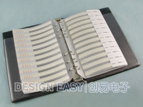
Design Easy SMD Component Books

Design Easy SMD Kit

These SMD component books are super handy for all sorts of electronics prototyping, construction, and repair projects. I bought a full set of these books for my lab bench at the office some time ago and and have found them invaluable. I liked them so much that I bought a second set for home!

R0402 kit detail

I prefer these component books over other types of SMD kits such as trays, bins, drawers, or bags because they don’t take up much space on the shelf and they keep components nicely organized in order by value.  Components are easy to access and hard to mix up.

There are many other vendors on eBay and aliexpress that sell component books just like these, but I like Design Easy because they have reasonable prices and carry resistor and capacitor assortments from size 1206 all the way down to 0201. You can save on shipping by ordering a complete set at once.

Here’s a snippet from their eBay store:

0402 practical book: ( resistor 63value 3300pcs )+( capacitor 17value 950pcs )
0603 practical book: ( resistor 63value 3025pcs )+( capacitor 17value 700pcs )
0805 practical book: ( resistor 63value 3025pcs )+( capacitor 17value 700pcs )
RF practical book:    ( 0402 capacitor 12value 600pcs ) + (0805 capacitor 10uF 50pcs ) + (0402 high F inductor 38value 1900pcs)
0201 resistors: 106 values, 50 pcs/value, 5300 pcs in all
0402 resistors: 170 values, 50 pcs/value, 8500 pcs in all
0603 resistors: 177 values, 50 pcs/value, 8850 pcs in all 5%
0603 resistors: 170 values, 50 pcs/value, 8500 pcs in all 1%
0805 resistors: 177 values, 50 pcs/value, 8850 pcs in all 5%
0805 resistors: 170 values, 50 pcs/value, 8500 pcs in all 1%
1206 resistors: 170 values, 50 pcs/value, 8500 pcs in all

0402 capacitors: 80 values, 50 pcs/value, 4000 pcs in all
0603 capacitors: 90 values, 50 pcs/value, 4500 pcs in all
0805 capacitors: 92 values, 50 pcs/value, 4600 pcs in all
1206 capacitors: 38 values, 50 pcs/value, 1900 pcs in all

Their “practical book” series contains an assortment of SMD resistors and capacitors in one book, while the separate resistor and capacitor kits are more complete and IMHO generally more useful, particularly if you use capacitors a lot and need a wider assortment of values.

Bonus: If you want to create your own component assortment or add extra pages to an existing one, Adafruit carries Blank SMT Storage Books and extra Storage Pages.

Bus Pirate v4 oscillates too. Tantalum cap to the rescue!

This week I finally received my Bus Pirate v4 from Seeed Studio.

The first thing I did after opening the box was to probe the 3.3V rail with the BP internal power supply enabled.

Here’s what I saw:

Bus Pirate v4 3.3V rail oscillation

That looks familiar!  Except this time it’s an oscillation at 5.9kHz and 400mVpp!  (almost 4 times what I saw on the SFE Bus Pirate).

I replaced C11 with a 4.7uF tantalum surface mount cap that I scavenged from another board, and the oscillation went away completely:

Bus Pirate v4 - C11 = 4.7uF tant


Ahh, that’s better!

Again, I strongly suspect the low ESR of the ceramic cap is to blame.  The 3.3V regulator really needs to see the higher ESR of a tantalum or electrolytic cap for stability.

My advice to all Bus Pirate owners is to check your 3.3V rail with a scope, if possible, and replace C11 with a tantalum or electrolytic cap.  Alternatively you may be able to add a small amount of resistance in series with the ceramic cap that comes with the Bus Pirate, but I haven’t verified this.


Simple fix for Bus Pirate power supply oscillations

Modified SFE Bus Pirate

I picked up this Sparkfun Bus Pirate a couple years ago (thanks to Free Day!) It sat in a box for most of its life until recently I needed a simple way to interface a PC to an I2C device at work.  Out came the Bus Pirate.

I’m fortunate to have an Agilent MSO-X 3000 series scope at the office. This scope includes I2C decode capability on both analog and digital channels. I had been having some trouble with corrupt data coming in on the digital channels, so before connecting the Bus Pirate I switched to using analog channels 1 and 2 to decode I2C clock and data instead.

After sending a few test packets with the Bus Pirate, I noticed something weird – the logic high level had a tiny sawtooth waveform riding on it. Not good.

I zoomed in and saw something like this:

without cap

That 15kHz sawtooth is almost 150 mVpp!

After removing my device under test, I quickly narrowed the problem down to noise on the Bus Pirate’s 3.3V rail. I initially suspected that this might be some kind of noise coming from the 5V USB supply, so I added an additional 10uF cap in parallel with the 1uF already on the board (C1). The sawtooth increased drastically in amplitude and went down sharply in frequency. That’s when I realized that this wasn’t noise, it was a power supply oscillation.

The Bus Pirate uses a Micrel MIC5025-3.3YM5 regulator (VR3 in this schematic) to create the 3.3V rail from USB’s 5V. In the datasheet, there is a familiar warning: “Ultra-low-ESR capacitors can cause a low amplitude oscillation on the output and/or underdamped transient response.” The Bus Pirate uses a ceramic cap for C1, I’m not sure of the type but it could easily be NPO/C0G and quite low ESR. Adding another 10uF ceramic cap lowered the ESR (and SRF) of the parallel combination, bad news for supply stability.

Realizing that low ESR of ceramic caps was likely part of the problem, I took a different approach. I went around the lab and found the crappiest cap I could find, a 1uF/50V electrolytic, and put that across C1 instead.

After adding the new cap, this is what the 3.3V rail looks like:

with cap

No more oscillation. This is with the original C1 still in place (see the photo at the top).

I don’t think Sparkfun has changed the design of their Bus Pirate clone in the years since I purchased mine, so if you’ve got one of these on your bench, throw a scope on the 3.3V DUT supply (after enabling it) and see what you find. You might be surprised.

Unless I am mistaken, a very similar regulator & bypass cap is used on all Dangerous Prototypes v3 and v4 Bus Pirates (including clones), so this is something to watch out for on any Bus Pirate on the wild.