When my renewal notice came in the mail, I was surprised to learn that I’ve had my ham radio license for just over ten years.
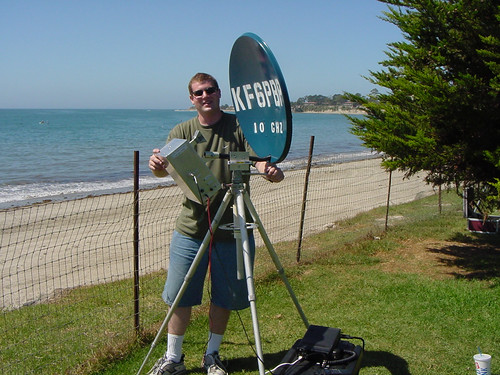
I received my Technician class license in college shortly after my classmate Tony introduced me to the world of amateur radio. I started out playing with TNC‘s and packet radio. Later, with Tony’s help, I built various microwave radios so I could participate in the very active San Diego Microwave Group. Some of my projects included a 10GHz transverter and a simple 24GHz wideband radio that used a surplus gunnplexer as an RF source, the same kind as found in police radar guns and many automatic door openers. (Please excuse my ancient webpages, they were cool ten years ago, ok?)
I also used to be somewhat active on 2m/440 and still have the Kenwood TH-79A radio my Dad bought me after I got my license. I still use it today, but not for voice communications. It has a new life now as part of my APRS Tracker project.
After seeing how many hams there were at NOTACON earlier this year, I finally decided it was time to upgrade my license to General class. This will give me more operating privileges on the HF bands, the traditional low frequency / long distance communication bands that are most commonly associated with amateur radio. My goal is to set up an HF station at home and maybe start playing with a Software Defined Radio system such as GNU Radio with custom homebrew hardware.
Before my trip to HAR I picked up a copy of the ARRL General Class License Manual and printed out a list of VE sessions in the Bay Area over the next couple of months. Now that I’m back, it’s time to start studying!
This is guest blogger Tony reporting on my latest project, a very small, precise circular chop saw. Why would anyone want to build such a saw you might ask? Well, to make parts for another project of course!
So here’s the background….I’m building a ham radio that operates at 47 GHz. At such a high frequency there are very few components that can be soldered on to circuit boards, let alone components that even come packaged! The easiest way to build a high performance radio at these frequencies is to use MMICs (Monolithic Microwave Integrated Circuits). These are really just fancy, yet fairly simple circuits made from exotic materials, most commonly Gallium Arsenide (GaAs) instead of the usual Silicon used for normal chips. Before MMICs were in widespread use, individual transistors had to be used, requiring delicate and hard to make external matching elements. MMICs are like nice little 50 ohm building blocks. Low Noise Amplifiers (LNAs), mixers, Power Amplifiers (PAs), phase shifters, etc. etc. are all available in this form. Trouble is that you have to connect these pieces up to make a functional radio (or at least the microwave portion of it).
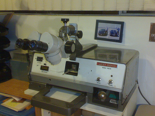
My WestBond wedge bonder
Wire bonding is the usual method for connection and is really just a method of welding a wire (or ribbon) from one chip to the next. It turns out that you actually need space in between the chips, for thermal reasons, RF reasons, and for placing the requisite bypass capacitors. So what goes in between the chips? Well, coax cable is pretty much out, and most common circuit board materials start getting pretty lossy at 10+ GHz, and even the good stuff (PTFE-based usually) starts getting kinda lousy at 40+ GHz. At very high frequencies, materials like ceramics and quartz become worthwhile. In my radio I chose to use pre-made alumina ceramic substrates (tiny circuit boards). These come with a gold layer on the back, and a gold line on top etched to perform as a 50 ohm transmission line (just like coax and just what the MMICs want to see). I bought these with a number of other hams last year in a group buy. They are fairly expensive being that they are 5 and 10 mils thick!
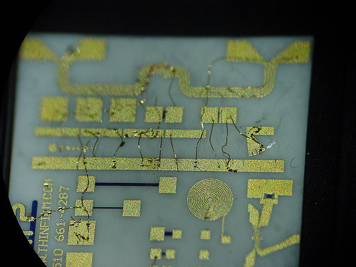
My first test bonds on an alumina ceramic substrate (ugly)
To make the best use of the sections that I bought I decided I needed to cut them to length. Well how do I do that? The thickest pieces are 10 mils thick (a piece of printer paper is 4 mils thick) and they are brittle! Beyond cutting, how do I hold the piece while cutting and when it’s done? The resulting pieces may be just 100 mils long, and 50 mils wide. Obviously a pair of vice-grips simply won’t do.
So my first thought was a Dremel tool and tape. This method could work, but it does not lend itself well to making measured cuts. At 47 GHz, a few hundredths of an inch is a lot! Also, the available diamond blades for dremel tools are fairly wide and I wanted to waste as little of the small substrates as possible. At this point I made a lucky find on eBay.
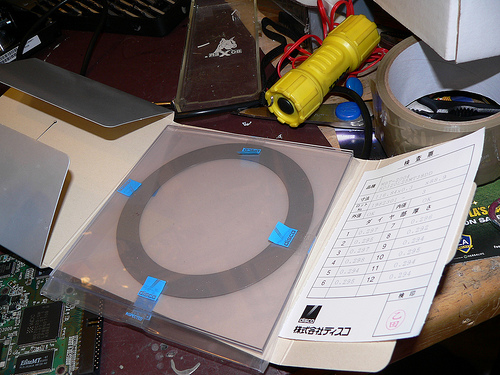
In the semiconductor industry, one of the last steps of making a chip is called “wafer dicing.” After a wafer full of chips is made, they need to be cut out into individual parts. To do this, wafer dicing machines were developed. These are CNC saws that use a high speed (as high as 60,000 rpm) air bearing spindles with diamond abrasive blades. They can cut lines across large dinner plate sized wafers that are as narrow as only a few tens of microns. Luckily there is enough wafer dicing going on in the world that there is a source of surplus blades on eBay. Not all blades are well suited for all materials, so do some research if you are interested. Disco (a Japanese company) is one of the largest dicing blade manufacturers.
Large (4.6 inch diameter) wafer dicing blade in it's packaging.
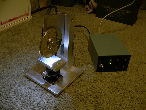
While reading the last paragraph you may have spotted a few words indicating unobtanium. Those words are “high speed air bearing spindle.” Well I chose to use a hard drive motor instead, because they have excellent bearings and are readily availble for free. While they don’t move as fast, I don’t care. I have a few short cuts to make, not millions of chips.
So that is an introduction to what I’m doing. For the most part the saw has been built using surplus parts and remnant pieces of metal from my favorite local metal supply house M&K Metals in lovely Gardena, CA. As of this entry, the saw is nearly complete, all that is left is the splash guards. I’ll be posting the build of this project in several parts, so stay tuned.
And a link to my Flickr photo set for this project: Dicing saw