Tag Archives: lcd

Building a Wifi Radio – Part 10, Building the Box

This is the tenth and final part of a series about building a low cost, open source streaming internet radio based on the ASUS WL-520gU Wireless Router.  If you haven’t already, check out the previous parts (see the links below) for some background about the project.

Wow, we’ve come a long way since part one!  To date, there have been nine parts in this series, each covering a different aspect of building the radio:

  1. Building a Wifi Radio – Part 1, Introduction
  2. Building a Wifi Radio – Part 2, Choosing an Embedded Platform
  3. Building a Wifi Radio – Part 3, Hacking the Asus WL-520GU
  4. Building a Wifi Radio – Part 4, Installing OpenWrt
  5. Building a Wifi Radio – Part 5, Let’s Make Some Noise!
  6. Building a Wifi Radio – Part 6, A Conversation with Mpd
  7. Building a Wifi Radio – Part 7, Building an LCD Display
  8. Building a Wifi Radio – Part 8, Adding a Tuning Control
  9. Building a Wifi Radio – Part 9, A Few Odds and Ends
  10. You are here.

Preface to Part 10:

In this part, I’m going to show you a few steps in the process I used to turn a wireless router, a breadboard, and a pile of loose parts into a finished standalone internet streaming radio receiver.  Unlike the previous parts in the series, I’m not going to provide detailed step by step instructions.  This is primarily because I don’t think it’s realistic to expect everyone to have access to the same tools and materials as I do.  Think of it this way – this is your opportunity to customize your radio.  Maybe you don’t like wood veneer, but prefer brushed aluminum or carbon fiber?  Maybe you have a laser cutter at your disposal and can turn a flat sheet of clear acrylic into a snap-together radio in less than 5 minutes?  This is your chance to express your creativity!  Go ahead and copy my design, but don’t be afraid to go off into left field either…

The Box:

Some time ago, I posted a Google Sketchup model of the radio enclosure that I created with the help of Tony, a good friend of mine who lives in Southern California.  The idea was to build a box out of wood to mimic the style of a vintage table radio.  All the components of the radio would be mounted inside the box, with the exception of the antenna (not shown).  We also wanted to add some custom touches to make the design look modern and unique, like black controls and flush mounted contoured speaker grilles and a minimalist front panel layout.

Here’s the model we came up with:

Wifi Radio Enclosure - Google Sketchup Model

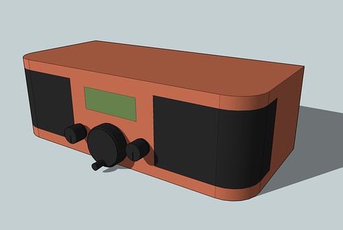
Tony and I spent a weekend in his garage near Los Angeles finalizing the design, cutting and bending sheets of plywood, making forms, and fitting various pieces of the box together.  Tony, who is far superior to me in the ways of woodworking and fabrication, did most of the work while I looked at stain colors and other details.

A few weeks later, Tony sent me this masterpiece.  Here’s the box, freshly stained and covered with many carefully sanded coats of polyurethane:

Wifi Radio Case Build

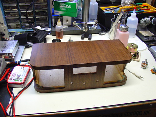
Hopefully Tony will write a post about the process of fabricating the box – he can provide a lot more details than I can.  For now, check out my photostream for some in-progress photos of the box.  Tony has some photos as well.

Once it arrived in the mail, it was up to me to combine the empty box with the pile of parts on my workbench to finish the project.

Finding an Audio Amplifier:

I wanted a small, inexpensive, stereo audio amplifier to mount inside the radio.  Originally, my goal was to find a kit with a few watts of power per channel, single supply operation (preferably with a common supply voltage, like 12V), volume and tone controls, and a compact PCB.  I never found any kits that I really liked (although I may look at 41hz for some future higher powered projects).  Eventually I gave up and bought a pair of used Altec Lansing ACS90 computer speakers for $5 from Weird Stuff in Sunnyvale, CA.

Altec Lansing PC Speakers

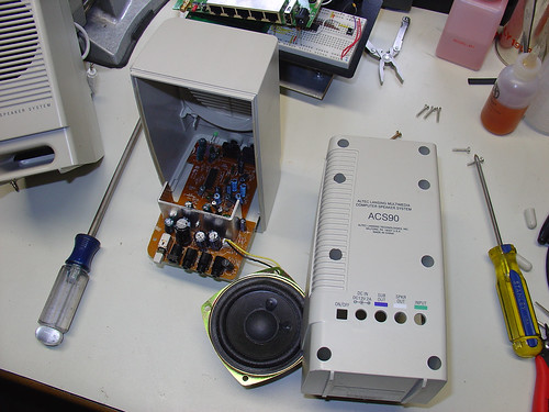
I took the speakers apart and threw away the plastic speaker boxes.  Inside one is a small stereo audio amplifier that runs on 12V @ < 2A and delivers 4W per channel.  I couldn’t ask for a better amp for this project, especially for the price!  I also salvaged the hefty speakers for reuse in the radio.

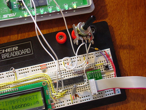
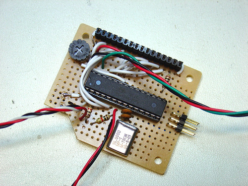
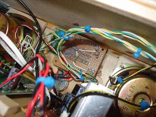
Building the LCD / Interface Circuit:

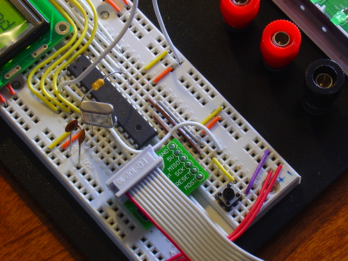
I carefully transferred my AVR microcontroller-based LCD driver / tuner control circuit from my breadboard to a piece of electronics protoboard.  Here’s the “component side” of the perfboard, showing the AVR ATmega168 microcontroller (socketed), 16MHz crystal, contrast trimpot, ICSP pins, and header socket for the LCD:

Wifi Radio - Final Assembly

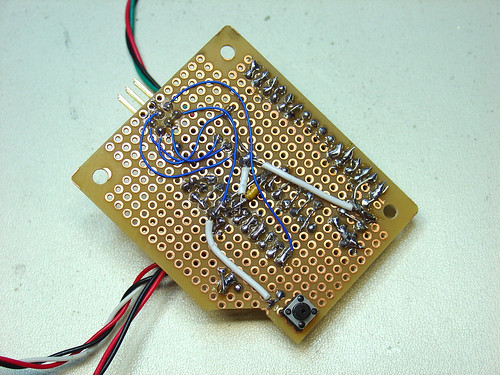
The “solder side” is mostly just interconnect wiring.  The RESET button is in the lower left corner.  I had to notch the PCB to clear one of the control pots inside the radio box.

Wifi Radio - Final Assembly

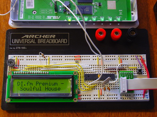
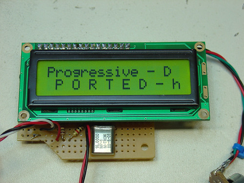
Here’s the protoboard with the LCD installed and being tested.

Wifi Radio - Final Assembly

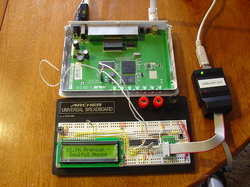
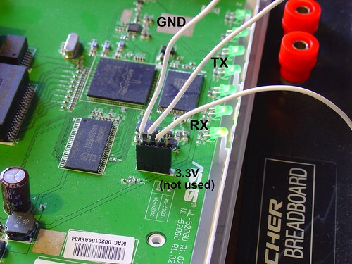
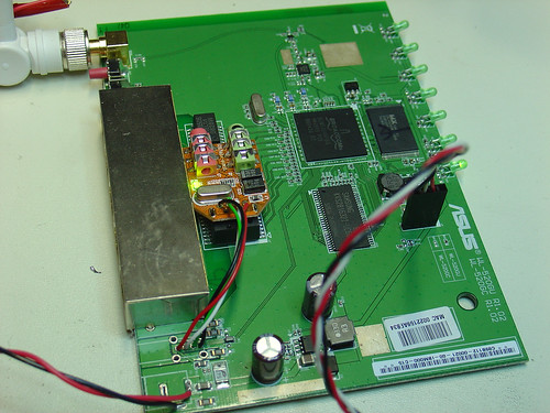
Modifying the router:

I removed the USB and DC power jacks from the WL-520gU PCB.  I’m planning to use the USB port solely to talk to my SYBA USB-Audio adapter, so I removed the USB connector from the SYBA as well and wired the USB lines directly to the router.  Some people may disagree with this, but wiring directly to the router simplified the wiring inside the radio and saved space by eliminating unnecessary USB connectors.  I can always put the USB jack back later if I want to connect other USB peripherals.  A pair of wires connects the DC power pins on the router to the radio’s 5V power supply.  Don’t attempt this unless you have a decent soldering iron – it’s easy to ruin the printed circuit board by overheating the traces.
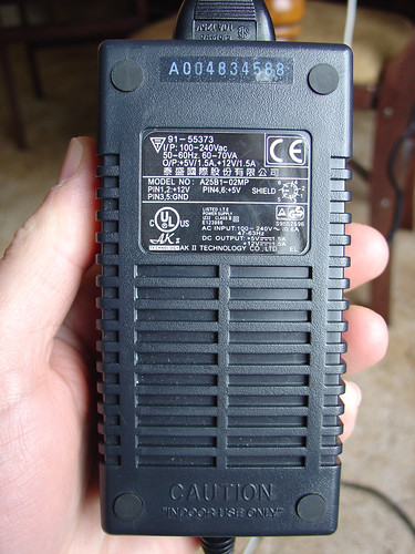
Wifi Radio - Final Assembly

The power supply:

To supply power to the radio, AVR microcontroller, and amplifier, I needed a power supply that could provide both 5V and 12VDC.  I found a used “brick” style power supply (also at Weird Stuff) rated at 5V and 12V @ 1.5A.  I believe this type of supply is very commonly used with external hard drive enclosures and shouldn’t be too hard to find.  Initially I was concerned that a switching supply would be too noisy to use with an audio amplifier, but a quick test showed no unexpected noise from the amp.

Wifi Radio Power Supply

Final assembly:

Mounting all of the components inside the radio box took a lot of time, epoxy, velcro, and hot glue.  Eventually I was able to get everything except the power supply to fit.  Although originally I had wanted to mount the supply inside the radio, keeping it external ensures that there is no 110V running around inside the box.  This is a nice safety feature, and I think it was a worthwhile compromise.

Wifi Radio - Final Assembly

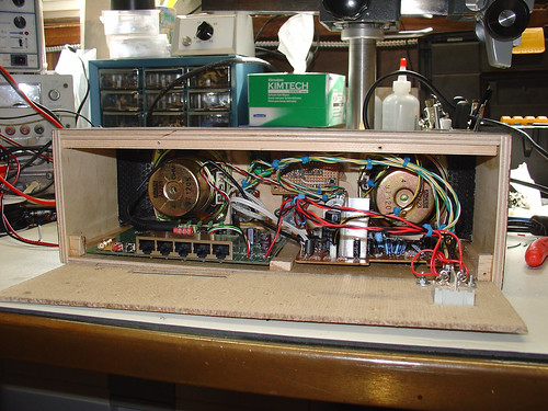
The router is mounted on the left side of the box.  I positioned it close to the back panel so that the antenna connector can pass through and the antenna can be attached.  The amplifier is on the right side.

Here’s a shot inside the box, showing the microcontroller circuit and LCD display.  The LCD is simply hot glued to the inside of the box.  You can also see the speakers mounted on either side of the display.

Wifi Radio - Final Assembly

The finished result:

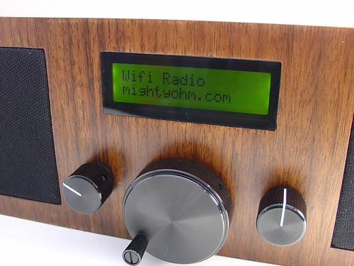
Here’s the front of the radio.  The LCD display is behind a thin sheet of smoked plexiglass that is press fit into the rectangular opening in the front panel.  The two smaller knobs are connected to potentiometers that I wired to the amplifier in place of the original controls.  The left knob controls volume, the right is for tone.  I originally wanted the volume knob to also be the power switch, but I couldn’t find a dual audio taper pot that included a switch as well.   The small knobs are from HSC in Sunnyvale.  The large knob in the center is the tuning control.  I spotted it at Mouser Electronics (#450-1755 / datasheet) and couldn’t resist using it on the radio.

Finished Wifi Radio

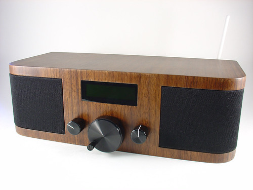
Here’s a closeup of the front panel with the LCD display powered on:

Finished Wifi Radio

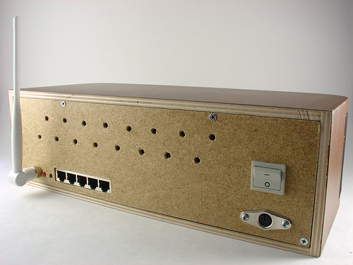
The back panel is made of fiberboard from Home Depot.  The Wi-Fi antenna is shown on the left.  The LAN ports and buttons of the router are accessible through cutouts in the back panel.  A 6-pin mini-DIN power jack that matches the power supply I’m using and the power switch are shown on the right.  Four screws hold the back panel onto the box, so it’s easy to remove.

Finished Wifi Radio

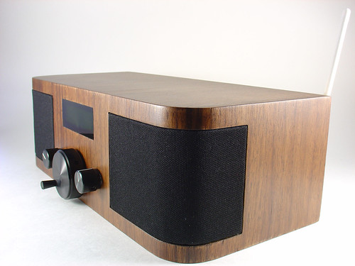
Here’s a side view showing the radio’s rounded corners and matching curved speaker grilles:

Finished Wifi Radio

Here’s a video of the radio in action, tuning between a few different preset stations, including Slay Radio, di.fm, and San Francisco’s somafm with Groove Salad.

There are a lot more pictures on Flickr.  Check them out and keep watching the Asus Wireless Router Hacks group for other people’s creations as well!

Conclusion:

This has been an epic journey.  Back in October, when I first posted about this project, I never anticipated how much interest there would be in creating a low-cost DIY wireless streaming radio.  I am really thankful for all of the encouragement I have received, both on this site and elsewhere.  Thanks to everyone who has visited from Make and Hack a Day, as well as everyone who complimented me on my talk at NOTACON.  You guys make it all worthwhile!

By the way, if you have questions or comments, join the forums!

Thanks for reading, and until next time, happy hacking!

– Jeff Keyzer aka mightyohm

Sneak peek at my finished Wifi Radio project!

While I’m busy working on part ten of my series on building a wireless router-based DIY streaming internet radio, I couldn’t resist sharing a few photos of the finished project.

If you want to see the radio in person, stop by Expo Hall Booth 166 at the Maker Faire in San Mateo, CA this weekend.  I’ll be there to demonstrate the radio and answer questions!

Finished Wifi Radio< Finished Wifi Radio

Finished Wifi Radio

Finished Wifi Radio

Building a Wifi Radio – Part 8, Adding a Tuning Control

This is the eighth part of an ongoing series about building a low cost, open source streaming internet radio based on the ASUS WL-520gU Wireless Router.  If you haven’t already, check out the previous parts (see the links at the end of this article) for some background about the project.

In part seven, we added an LCD status display for the radio that shows the stream name as well as the artist and title of the current track.  In this part, we’ll add a tuning knob that lets us change stations without using a computer.

It turns out that this is mostly a software exercise, made simple by taking advantage of the analog to digital converter function of the Atmel ATmega168 AVR that is controlling the LCD display.  The addition of the tuner control turns the display circuit into a very simple user interface.  Turn the knob and the station changes.  The position of the knob determines what station the radio is “tuned” to, and when combined with a calibrated scale it will make it easy to change to any one of the several streaming radio stations stored as presets (favorites?) in the router.

To give you an idea of how this works, here is a demo of the tuner control changing between ten preset stations I have set on the router.  The tuner control is in the upper right hand corner of the breadboard.  As I adjust the control, the music changes and LCD display updates to show the name of each new station.

Is that cool or what?

If you are interested in adding this functionality to the radio, keep reading and I’ll show you how.

Changes to the hardware:

You will need:

  • The completed AVR-based LCD display from part seven
  • A 1k-10k trimmer or potentiometer, linear taper
  • Some hookup wire

Schematic:

Here is an updated schematic of the AVR circuit showing the potentiometer connected to ADC4 (pin 27).

Wifi Radio User Interface Schematic
click to enlarge

Firmware:

The AVR firmware has been significantly expanded, slightly reworked and cleaned up in some areas.

The most important changes are:

  • The addition of a serial transmit function so the AVR can talk to the router (based on the uart_putchar function)
  • New code supporting the analog to digital converter (ADC) which reads the value of a potentiometer connected to ADC4.
  • A new Timer1 overflow interrupt has been added, which occurs roughly every 0.5 seconds.  The interrupt service routine (ISR) checks the position of the tuner control, and if it has changed, sends the value to the router.  The ISR is towards the top of the file, see the SIGNAL (TIMER1_OVF_vect) section.

The ADC range of the ATmega is 0 – 1024 for an input voltage from 0 to 5V.  The AVR sends serial data in the format “Tuner: Value” back to the router when the tuner position changes by more than ADC_SENS counts (default is 5).  The AVR waits for an “AVR Start!” command from the router before sending any data, this avoids filling up the serial receive buffer on the router before it’s ready to start processing data.  An important consequence of this is that the AVR must be reset before running the control script on the router.

You can download the source code and compiled .hex file here.  Flash it to the AVR using any compatible ISP programmer and you should be good to go.  The source is commented fairly well so if you’re interested in learning how the interface works, take a look.  You will need a copy of the ATmega168 datasheet to understand the register names and other architecture-specific parts of the code.  Feel free to post in the comments with any questions.

Modifying the circuit:

This part is pretty simple – just wire the potentiometer as shown in the schematic.  Most potentiometers have three terminals.  The left terminal goes to ground, the right one to +5V, and the middle terminal to ADC4 on the AVR (pin 27).

Tuner control on breadboard

Tweaks to the OpenWrt configuration:

To make bidirectional communication with the AVR work, we have to change a couple config files on the router and disable some services that would otherwise get in the way.

/etc/config/network

The first change is to modify the /etc/config/network file so that we can always telnet or ssh into the router on a LAN port using the IP 192.168.1.1.  The ability to access the router via ethernet is helpful in case we screw something up and lose the wireless connection or the router loses it’s IP address, etc.

Modify the LAN section of /etc/config/network to look like this (changes in bold):

#### LAN configuration
config interface lan
#option type     bridge
option ifname    "eth0.0"
option proto    static
option ipaddr    192.168.1.1
option netmask    255.255.255.0

Save changes, restart the router, and connect an ethernet crossover cable (straight cable might work on some computers) to the router.  Configure your desktop/laptop computer with a static IP, like 192.168.1.185.  Try to open a telnet connection (or ssh if you have set a password on the router) and see if you can log in.  If not, don’t continue with the next steps until you can get this working.

/etc/inittab

We previously used the router’s serial port to get a login shell.  Now that we’re trying to receive data from the AVR on the same serial port, we need to disable the login shell or it will capture the data before we can get to it.

Edit /etc/inittab to look like this (changes in bold):

::sysinit:/etc/init.d/rcS S boot
::shutdown:/etc/init.d/rcS K stop
#tts/0::askfirst:/bin/ash --login
#ttyS0::askfirst:/bin/ash --login
tty1::askfirst:/bin/ash --login

/etc/sysctl.conf

Sysrq is a fascinating and very low level debugging feature of the Linux kernel.  It can be used to perform troubleshooting operations and reboot the system.  Usually it is invoked with a magic key combination on a desktop computer, but in this case I found that it is easy to accidentally trip over the serial port when using an AVR.  (The “break” RS-232 code triggers Sysrq, this probably has something to do with it.)

Fortunately, it’s easy to disable by editing the /etc/sysctl.conf file and adding these lines:

# Disables the magic SysRq key
kernel.sysrq = 0

Reboot the router to apply the changes.  Now we can get on with the good stuff!

Shell scripting magic:

The real action happens on the router, where a shell script waits for input from the router and changes the station accordingly.

This script is called interface.sh and can be downloaded to the router using wget as shown:

root@OpenWrt:~# cd ~
root@OpenWrt:~# wget http://mightyohm.com/files/wifiradio/interface.sh
...
root@OpenWrt:~# chmod ugo+x interface.sh

The interface script calls an updated version of the display script from part 7, called display2.sh:

root@OpenWrt:~# wget http://mightyohm.com/files/wifiradio/display2.sh
...
root@OpenWrt:~# chmod ugo+x display2.sh

Once both scripts are downloaded, executable and located in /root you can launch interface.sh as follows:

root@OpenWrt:~# ./interface.sh
volume: 60%   repeat: on    random: off
adding: http://relay3.slayradio.org:8000/
adding: http://scfire-dtc-aa01.stream.aol.com:80/stream/1046
adding: http://208.101.28.234:8004

… more stations here …

Tuner Position:  0
New station...
http://relay3.slayradio.org:8000/
[playing] #1/10   0:00/0:00 (100%)
volume: 60%   repeat: on    random: off

The interface script adds ten presets to the router, shows the playlist, and then waits for valid tuner data from the AVR.  Once it receives a “Tuner: value” line (which should occur shortly after the AVR receives a go signal from the script), the script prints the received tuner positon and changes to the requested station.  It will then wait for new tuner data from the AVR and change the station when necessary.

As you can see in the video, this works very well.  Over a fast Wi-Fi connection, the time to change stations is almost instantaneous – very satisfying!

That’s it for part eight.  In part nine, I’ll add some finishing touches to the router configuration and start talking about enclosures.  Stay tuned!

Update: There is a new Wifi Radio Discussion Forum, hop over there to ask questions about the project or see what other people are working on!  (4/12/09)

Update 2: Part nine is now available.

Building a Wifi Radio – Part 7, Building an LCD Display

This is the seventh part of an ongoing series about building a low cost, open source streaming internet radio.  If you haven’t already, check out the previous parts (see the links at the end of this article) for some background about the project.

In part six, we used OpenWrt’s UNIX-style shell commands to interface with mpd, the music player daemon, and redirect song and stream information to our ASUS WL-520gU wireless router’s serial port.  In this part, we’ll use a Sparkfun 16×2 LCD display and a handful of other components to build an LCD status display for the radio.

The Atmel AVR Microcontroller:

After much thought, I decided to use an Atmel ATmega168 AVR microcontroller to drive the display.  I realize that this raises the technical level of this project significantly, but I have been wanting to feature an AVR project on the site and this is a great opportunity.  The truth is that an Arduino would work just as well and it shouldn’t be too difficult to port this program to an Arduino sketch.  (The Arduino is built with the same ATmega168 microcontroller, after all.)  If anyone does this, let me know and I’ll post a link to your version of the display.

If you’re an AVR veteran, you can skip over this part and straight to the bill of materials below.

If you are new to the AVR, don’t be intimidated.  There are a number of tutorials online to help you learn how to use this inexpensive and powerful microcontroller.  I recommend starting with this one or maybe this one, but see my note about AVR MacPack below if you’re using a Mac.  If you’ve never programmed in C before, you’ll have an additional hurdle to get over, although for this project you won’t need any actual knowledge of programming or C to burn the code to the AVR and get things working.

You will need to install some software to work with the AVR, I recommend:

  • AVR MacPack for OS X (the Adafruit tutorial recommends OSX-AVR, use this instead)
  • WinAVR for Windows

I recommend following a tutorial or two and getting a simple blinking LED example working on your AVR before building the LCD display.  That way you can be sure your programmer, development environment, breadboard, etc are working first.

Building the display:

Bill of Materials:

You will need:

also nice, but not required:

  • a Sparkfun ISP breakout board to simplify connecting the programmer to the breadboard
  • a normally-open pushbutton switch to reset the circuit

Schematic:

Here is the schematic of the LCD display (click to enlarge):

Wifi Radio LCD Display Schematic

Firmware:

You can download the source code and compiled .hex file here.

Special thanks to Peter Fleury for his excellent LCD library, which saved me from reinventing the wheel!  He also has another page about interfacing LCD displays to an AVR.

Assembling the circuit:

Assembling the circuit on the breadboard is pretty straightforward.  Here’s a photo showing all components of the setup.  The router is shown above with the serial port wired to the breadboard (the RX line is floating as we’re not using it yet).  The USB AVR programmer is on the right, where it is also functioning as a 5V power supply for the circuit. Make sure the 2-pin jumper on the USBTinyISP is installed, this enables the +5V supply.  The LCD is shown displaying the current stream name (DI.fm).

Wifi Radio LCD Display

Here is a closeup of the components installed on the breadboard to show how I did things, feel free to experiment with the placement of components.  As long as you follow the schematic the circuit should still work.

Wifi Radio LCD Display

Here is a closeup of the serial port connection to the router, including the 4-pin female 0.1″ header.  I soldered wires to the pins of the female header (not the pins on the board).

Wifi Radio LCD Display

Here is a closeup of the AVR, crystal, and the Sparkfun ISP breakout board showing the pinout:

Wifi Radio LCD Display

Flashing the AVR:

Once the circuit is assembled on the breadboard, we need to flash the AVR microcontroller with the main.hex file included with the firmware above.

If you’re using AVR MacPack and OS X, this should be easy (since that’s what I’m using).  PC guys will need to figure this out for themselves but hopefully the process is similar (please let me know if the Makefile works).

Connect the USBTinyISP to your computer with the USB cable and to the breadboard with the ISP cable.  The green light on the programmer should be on, indicating it is ready, and the backlight of the LCD should be lit, indicating that the breadboard is getting power.

Open a terminal window and create a new directory, I used ~/temp.  Unzip the firmware into a directory somewhere, and execute ‘make flash’, as shown:

macbook:temp jkeyzer$ unzip ./AVR_wifiradio_display.zip
Archive:  ./AVR_wifiradio_display.zip
  inflating: lcd.c
  inflating: lcd.h
  inflating: main.c
  inflating: main.hex
  inflating: Makefile
macbook:temp jkeyzer$ make flash
avr-gcc -Wall -Os -DF_CPU=16000000 -mmcu=atmega168  -c main.c -o main.o

a few warnings later …

avr-gcc -Wall -Os -DF_CPU=16000000 -mmcu=atmega168  -c lcd.c -o lcd.o
avr-gcc -Wall -Os -DF_CPU=16000000 -mmcu=atmega168  -o main.elf main.o lcd.o
rm -f main.hex
avr-objcopy -j .text -j .data -O ihex main.elf main.hex
avrdude -c usbtiny -p atmega168 -U flash:w:main.hex:i
avrdude: AVR device initialized and ready to accept instructions
Reading | ################################################## | 100% 0.01s
avrdude: Device signature = 0x1e9406
avrdude: NOTE: FLASH memory has been specified, an erase cycle will be performed
         To disable this feature, specify the -D option.
avrdude: erasing chip
avrdude: reading input file "main.hex"
avrdude: writing flash (1326 bytes):
Writing | ################################################## | 100% 3.32s
avrdude: 1326 bytes of flash written
avrdude: verifying flash memory against main.hex:
avrdude: load data flash data from input file main.hex:
avrdude: input file main.hex contains 1326 bytes
avrdude: reading on-chip flash data:
Reading | ################################################## | 100% 0.68s
avrdude: verifying ...
avrdude: 1326 bytes of flash verified
avrdude: safemode: Fuses OK
avrdude done.  Thank you.

If everything went well, the LCD display firmware is now loaded into the ATmega168 and the circuit is ready to go.  If not, double check your connections and take a look at the help! page for the USBTinyISP.

Testing the display:

Telnet or ssh into the router.  Start mpd and connect to a stream using mpc (we covered this in part five).

Once the stream starts playing, execute the display.sh script we created in part six.  Within a few seconds, if everything is working, you should see the stream name on the display, followed by the artist and name of the current song.  Congratulations!

Here is a video of the LCD display in action, including the horizontal scrolling feature to show information that is too wide to fit within the visible area of the display:

That’s it for part seven!  In part eight, we’ll start working on the input side of the user interface.

Like what you’re seeing?  Have suggestions about what could be improved?  Leave a comment or contact me directly.

Update: Part eight, in which I add a tuning control to the radio, is now available.

Update 2: There is a new Wifi Radio Discussion Forum, hop over there to ask questions about the project or see what other people are working on!  (4/12/09)