Did my Wifi Radio project inspire you to buy a wireless router and start hacking? If so, I’d like to hear from you!
Leave a comment below and let me know how your project is coming along. Even if you’re not building a Wifi Radio but used my firmware or tutorials as a starting point (a great example is the Tweet-a-Watt), I’d love to hear from you.
If you have photos of your project, you can share them with the world by adding them to the Asus Wireless Router Hacks photo pool on flickr.
This is the tenth and final part of a series about building a low cost, open source streaming internet radio based on the ASUS WL-520gU Wireless Router. If you haven’t already, check out the previous parts (see the links below) for some background about the project.
Wow, we’ve come a long way since part one! To date, there have been nine parts in this series, each covering a different aspect of building the radio:
In this part, I’m going to show you a few steps in the process I used to turn a wireless router, a breadboard, and a pile of loose parts into a finished standalone internet streaming radio receiver. Unlike the previous parts in the series, I’m not going to provide detailed step by step instructions. This is primarily because I don’t think it’s realistic to expect everyone to have access to the same tools and materials as I do. Think of it this way – this is your opportunity to customize your radio. Maybe you don’t like wood veneer, but prefer brushed aluminum or carbon fiber? Maybe you have a laser cutter at your disposal and can turn a flat sheet of clear acrylic into a snap-together radio in less than 5 minutes? This is your chance to express your creativity! Go ahead and copy my design, but don’t be afraid to go off into left field either…
The Box:
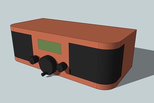
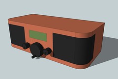
Some time ago, I posted a Google Sketchup model of the radio enclosure that I created with the help of Tony, a good friend of mine who lives in Southern California. The idea was to build a box out of wood to mimic the style of a vintage table radio. All the components of the radio would be mounted inside the box, with the exception of the antenna (not shown). We also wanted to add some custom touches to make the design look modern and unique, like black controls and flush mounted contoured speaker grilles and a minimalist front panel layout.
Here’s the model we came up with:
Tony and I spent a weekend in his garage near Los Angeles finalizing the design, cutting and bending sheets of plywood, making forms, and fitting various pieces of the box together. Tony, who is far superior to me in the ways of woodworking and fabrication, did most of the work while I looked at stain colors and other details.
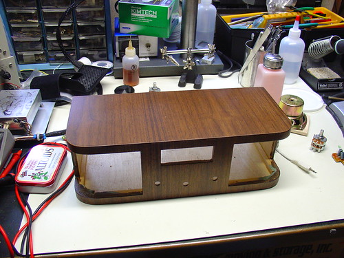
A few weeks later, Tony sent me this masterpiece. Here’s the box, freshly stained and covered with many carefully sanded coats of polyurethane:
Hopefully Tony will write a post about the process of fabricating the box – he can provide a lot more details than I can. For now, check out my photostream for some in-progress photos of the box. Tony has some photos as well.
Once it arrived in the mail, it was up to me to combine the empty box with the pile of parts on my workbench to finish the project.
Finding an Audio Amplifier:
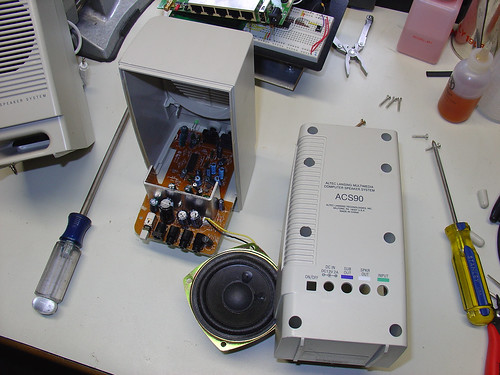
I wanted a small, inexpensive, stereo audio amplifier to mount inside the radio. Originally, my goal was to find a kit with a few watts of power per channel, single supply operation (preferably with a common supply voltage, like 12V), volume and tone controls, and a compact PCB. I never found any kits that I really liked (although I may look at 41hz for some future higher powered projects). Eventually I gave up and bought a pair of used Altec Lansing ACS90 computer speakers for $5 from Weird Stuff in Sunnyvale, CA.
I took the speakers apart and threw away the plastic speaker boxes. Inside one is a small stereo audio amplifier that runs on 12V @ < 2A and delivers 4W per channel. I couldn’t ask for a better amp for this project, especially for the price! I also salvaged the hefty speakers for reuse in the radio.
Building the LCD / Interface Circuit:
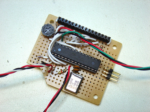
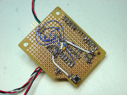
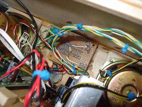
I carefully transferred my AVR microcontroller-based LCD driver / tuner control circuit from my breadboard to a piece of electronics protoboard. Here’s the “component side” of the perfboard, showing the AVR ATmega168 microcontroller (socketed), 16MHz crystal, contrast trimpot, ICSP pins, and header socket for the LCD:
The “solder side” is mostly just interconnect wiring. The RESET button is in the lower left corner. I had to notch the PCB to clear one of the control pots inside the radio box.
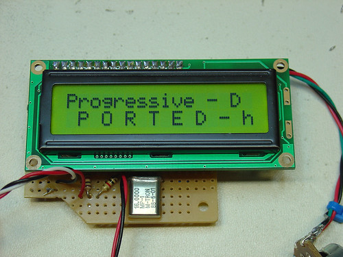
Here’s the protoboard with the LCD installed and being tested.
Modifying the router:
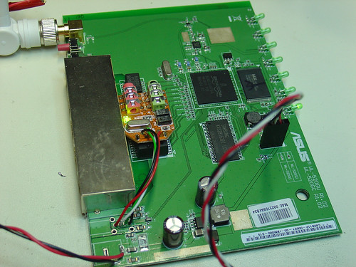
I removed the USB and DC power jacks from the WL-520gU PCB. I’m planning to use the USB port solely to talk to my SYBA USB-Audio adapter, so I removed the USB connector from the SYBA as well and wired the USB lines directly to the router. Some people may disagree with this, but wiring directly to the router simplified the wiring inside the radio and saved space by eliminating unnecessary USB connectors. I can always put the USB jack back later if I want to connect other USB peripherals. A pair of wires connects the DC power pins on the router to the radio’s 5V power supply. Don’t attempt this unless you have a decent soldering iron – it’s easy to ruin the printed circuit board by overheating the traces.
The power supply:
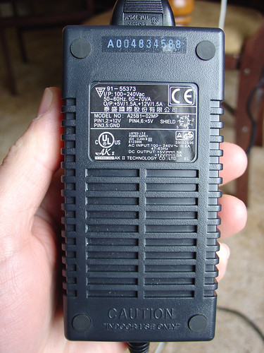
To supply power to the radio, AVR microcontroller, and amplifier, I needed a power supply that could provide both 5V and 12VDC. I found a used “brick” style power supply (also at Weird Stuff) rated at 5V and 12V @ 1.5A. I believe this type of supply is very commonly used with external hard drive enclosures and shouldn’t be too hard to find. Initially I was concerned that a switching supply would be too noisy to use with an audio amplifier, but a quick test showed no unexpected noise from the amp.
Final assembly:
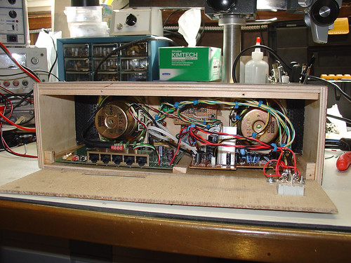
Mounting all of the components inside the radio box took a lot of time, epoxy, velcro, and hot glue. Eventually I was able to get everything except the power supply to fit. Although originally I had wanted to mount the supply inside the radio, keeping it external ensures that there is no 110V running around inside the box. This is a nice safety feature, and I think it was a worthwhile compromise.
The router is mounted on the left side of the box. I positioned it close to the back panel so that the antenna connector can pass through and the antenna can be attached. The amplifier is on the right side.
Here’s a shot inside the box, showing the microcontroller circuit and LCD display. The LCD is simply hot glued to the inside of the box. You can also see the speakers mounted on either side of the display.
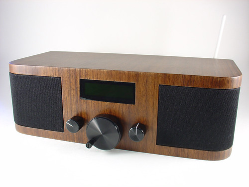
The finished result:
Here’s the front of the radio. The LCD display is behind a thin sheet of smoked plexiglass that is press fit into the rectangular opening in the front panel. The two smaller knobs are connected to potentiometers that I wired to the amplifier in place of the original controls. The left knob controls volume, the right is for tone. I originally wanted the volume knob to also be the power switch, but I couldn’t find a dual audio taper pot that included a switch as well. The small knobs are from HSC in Sunnyvale. The large knob in the center is the tuning control. I spotted it at Mouser Electronics (#450-1755 / datasheet) and couldn’t resist using it on the radio.
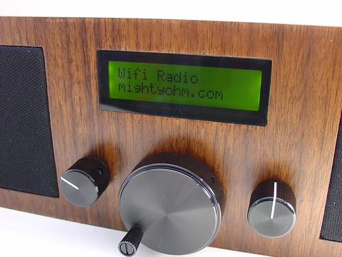
Here’s a closeup of the front panel with the LCD display powered on:
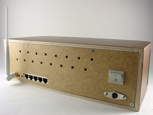
The back panel is made of fiberboard from Home Depot. The Wi-Fi antenna is shown on the left. The LAN ports and buttons of the router are accessible through cutouts in the back panel. A 6-pin mini-DIN power jack that matches the power supply I’m using and the power switch are shown on the right. Four screws hold the back panel onto the box, so it’s easy to remove.
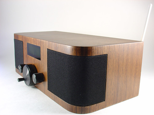
Here’s a side view showing the radio’s rounded corners and matching curved speaker grilles:
Here’s a video of the radio in action, tuning between a few different preset stations, including Slay Radio, di.fm, and San Francisco’s somafm with Groove Salad.
This has been an epic journey. Back in October, when I first posted about this project, I never anticipated how much interest there would be in creating a low-cost DIY wireless streaming radio. I am really thankful for all of the encouragement I have received, both on this site and elsewhere. Thanks to everyone who has visited from Make and Hack a Day, as well as everyone who complimented me on my talk at NOTACON. You guys make it all worthwhile!
By the way, if you have questions or comments, join the forums!
Thanks for reading, and until next time, happy hacking!
If you want to see the radio in person, stop by Expo Hall Booth 166 at the Maker Faire in San Mateo, CA this weekend. I’ll be there to demonstrate the radio and answer questions!
This is the ninth part of an ongoing series about building a low cost, open source streaming internet radio based on the ASUS WL-520gU Wireless Router. If you haven’t already, check out the previous parts (see the links at the end of this article) for some background about the project.
In part eight, we added a tuning control for the radio. Now we can change to any of ten preset stations on the radio by adjusting the position of a potentiometer connected to our AVR microcontroller. The LCD display we built in part seven lets us know what stream we’re listening to and the artist and title of the current song. This project is coming together very nicely!
Before we put the final touches on this project in part ten, there are a few miscellaneous chores to take care of:
Fixing /etc/config/wireless:
Last time, we tweaked /etc/config/network to assign a static IP address to the LAN (ethernet) ports of the router. This allowed us to directly connect a computer to the router via an ethernet cable and get a shell prompt, regardless of the state of the serial console or the wireless connection of the router. Unfortunately, I made an omission in the setup instructions which may prevent this from working correctly.
To fix this, modify /etc/config/wireless as follows (changes are in bold, use your wireless network information in place of my example):
config wifi-device  wl0
    option type     broadcom
    option channel  3

    # REMOVE THIS LINE TO ENABLE WIFI:
    # option disabled 1

config wifi-iface
    option device   wl0
    option network  wan
    option mode     sta  # configures the router to connect to your network
    option ssid     MyNetwork # the SSID of your network
    option encryption wep  # the encryption mode of your network
    option key	XXXXXXXXXX  # add this line with your WEP key in place of X...X
The only change is to set “option network” to “wan” instead of “lan”. This minor change tells the router to separate the wireless interface of the router from the LAN/ethernet interface and allows the router to acquire two separate IP addresses, one for each interface.
Launching mpd automatically at startup:
Manually launching mpd every time the router boots is a drag. You can automate this by creating a symbolic link to /etc/init.d/mpd from the /etc/rc.d directory, as follows:
Now every time the router boots, mpd will be started automatically as part of the boot process. (That was easy!)
Boot script for the user interface:
Assuming we want a dedicated internet radio that doesn’t require user intervention to operate, the scripts for the LCD display and tuning control should also be launched at startup. This will ensure that upon applying power, the radio will boot into a state where a stream is playing and the user interface is active.
First, we need to create a simple boot script. Create the file /etc/init.d/AVR with the following contents:
Every time the router boots, the user interface will automatically start, mpd will start playing the selected stream based on the tuner position, and the AVR microcontroller (assuming it is still connected to the serial port) will update the LCD display and watch the potentiometer for any changes in position.
Tweaking the firewall configuration:
This is actually optional, but it can be pretty useful while hacking on the router. As presently configured, the router blocks incoming requests on the WAN, which now includes the wireless interface. This prevents us from using ssh or telnet to log into the router over our wireless network. While we can still get a shell by connecting an ethernet cable to one of the LAN ports on the router, it is often more convenient to access the router across your wireless network.
The file /etc/config/firewall controls the firewall settings. We’ll be modifying this file.
Open the file in vi and scroll down to this section:
config zone
    option name        wan
    option input    REJECT
    option output    ACCEPT
    option forward    REJECT
    option masq        1
Edit the “option input” line so that it looks like this:
config zone
    option name        wan
    option input    ACCEPT
    option output    ACCEPT
    option forward    REJECT
    option masq        1
Now restart the firewall (or just reboot the router):
root@OpenWrt:~# /etc/init.d/firewall restart
You should now be able to ssh or telnet into the router over your wireless network.
Enable SSH:
By the way, if you want to access the router with ssh instead of telnet, just set a root password. The telnet daemon will be disabled (for security reasons) and replaced with an SSH daemon instead. You can do this with the “passwd” command.
root@OpenWrt:~# passwd
Changing password for root
New password: *****
Retype password: *****
Password for root changed by root
root@OpenWrt:~#
Log out of your telnet session and use ssh to log back in with your favorite ssh client (don’t forget to tell the client to use the username “root”).
Stay tuned!
That’s it for now. Stay tuned for the final part in this series, part ten, in which I’ll talk about what it took to turn this Sketchup model into a real wooden case for the radio!
Update: Part ten (the final part in the series) is now online.
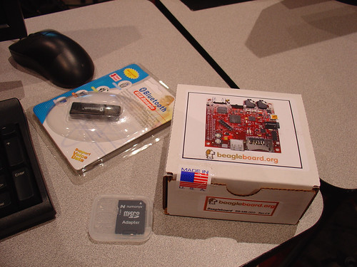
When I picked up my conference registration on-site, I also received a Beagle Board dev kit which included a 2GB SD card, a Class 1 Bluetooth USB adapter, and a tiny box containing a brand new Rev C2 Beagle Board. This was pretty exciting, given that the C2 boards haven’t even hit Digikey yet, making me one of a select group to have a C2 board!
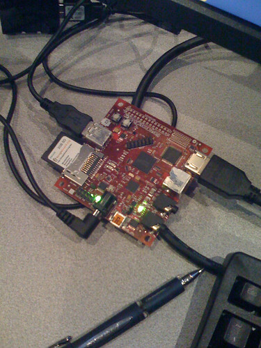
Here’s a photo of the kit as provided by ESC.
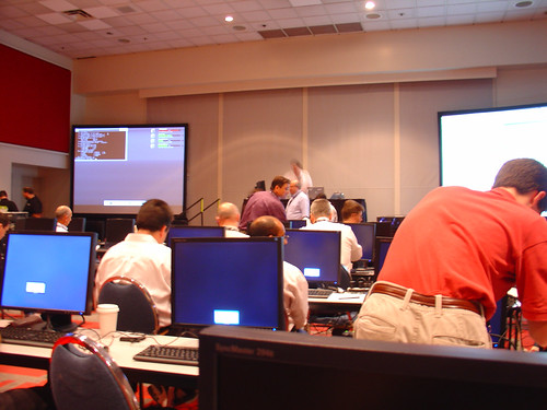
The classroom was full of LCD monitors, keyboards, mice, and USB hubs – but no computers. This is where the Beagle Board comes in.
The first step was to plug the peripherals into the board, as shown below. The HDMI interface for the LCD is at the upper right of the board, while the SD card and USB host port is on the left. The bottom of the board has a DC power jack and the USB OTG port which we used later. The whole board is actually powered via USB – the other end of the cable with the DC plug goes into the USB hub, and the hub powers everything. Pretty cool.
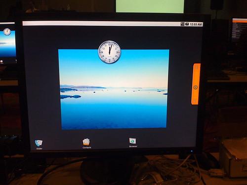
The classes were fantastic. I saw lots of really impressive demos, including some really neat 3D graphics using the onboard OMAP35x SGX 2D/3D graphics accelerator.
I particularly enjoyed the Monday morning class, led by Beagle Board designers Jason Kridner and Gerald Coley. Jason gave an overview of both the impressive feature list of the board and the large development community behind beagleboard.org. Gerald talked about the hardware development process, including some of the difficulties with the OMAP3 processor, which uses PoP technology. The system memory chip is soldered to pads on top of the CPU, which is then soldered to the PCB. Not surprisingly, this process took some optimization to get right.
Some observations:
While the Beagle Board was developed by engineers at Texas Instruments, TI does not officially support the board, which is more of a technology demonstration. Instead, people using the board can go to the beagleboard.org community for support, where there is a vibrant community of volunteer developers.
The philosophy behind the hardware is “Bring your own”. The board contains a minimum set of peripherals and you attach what you want. Apparently most eval boards contain a lot of features people never use (cameras, wireless interfaces, etc.) and tend to force desigers into using only the “supported devices”.
The hardware is open source. You can download gerbers, Allegro files, schematics, etc from their site. (Sadly, no Eagle files, although the 6 layer PCB wouldn’t be supported by the cheap/free versions of the Eagle anyway.) You can develop products based on the Eagle board and just stick copies of the design into your own PCB, or develop your own design.
The Beagle Board is not recommended/supported for use in production hardware. It’s for evaluation only. If you develop a product, you’re supposed to handle your own PCB builds, etc. The good news is, you can call up their contract manufacturer (CircuitCo) directly and get a batch of Beagle Boards made if you want to use the hardware as-is.
The communiy is very good about having mutliple avenues for discussion and collaboration. They are leveraging lots of old and new technologies: IRC, a wiki, a mailing list, delicio.us social bookmarking, RSS, etc etc etc. All of these are accessible from beagleboard.org.