Tag Archives: microscope

Cool Tools: Dino-Lite AM4113T USB Digital Microscope

61V-Rea54FL._SL1000_

The Dino-Lite Pro AM4113T 1.3MP Handheld Digital Microscope is a surprisingly handy tool for inspecting all sorts of fine details at home and on the road. The small size and light weight are ideal for travel. I keep this microscope along with several other tools in my “go box” of electronics supplies for overseas travel.

Dino-Lite offers a wide variety of digital microscopes with a similar basic design to the AM4113T but varying resolution and other features.  This particular model is not cheap ($399), but the extra resolution and features of the “Premier” series scopes are handy.  If you don’t need these features, there are several lower cost options available, including the lower resolution AM311S (which I have not used myself but gets generally positive reviews).

Here’s a sample image from the AM4113T (converted to jpg but otherwise unmodified):

A108 - 20150401_200212

The included Dino Capture software is surprisingly usable and allows you to take instant snapshots and videos and make a number of measurements and annotations directly within the tool (only supported on the more expensive Premier series).  This is super handy for field work.  For example, here’s a measurement of the angle of a USB connector relative to a PCB edge.

Capture


The USB 2.0 interface is fast and responsive which makes the critically important live preview (there is no viewfinder) a pleasure to use. There is a handy touch-activated sensor on the side of the scope for quick snapshots. (Pro-tip: mark which direction is “up” with a sharpie or you’ll get dizzy trying to orient the cylindrical scope every time you use it.)

Compared to more inexpensive USB microscopes, like the Andonstar OT-V1, the Dino-Lite offers significantly better image quality, one touch snapshots, a better focus mechanism, and better, more uniform illumination.

One disappointment is the very obvious rolling shutter, which is particularly annoying when the microscope is being used to make measurements without a stand. At this price point, I would have expected a sensor with a global shutter. Despite this limitation, the Dino-Lite AM4113T is still a very useful tool and has already helped me make some critical measurements in the field.

AO StereoStar Microscope Wiki Page

Today, while I was tweaking the microscope that I use for surface mount soldering, I realized that I have collected quite a bit of hard to find information about this circa~1975 model 569 American Optical StereoStar Stereoscopic Zoom Microscope (say that three times fast!).

So, I made a wiki page and put it all online.  StereoStar owners, rejoice!

AO StereoStar Stereo Zoom Microscope Resources

Improvements to my microscope setup for SMT work

Why do I need a microscope for SMT?

The single biggest challenge to doing “real” SMT work (0805 or smaller components and fine lead pitch ICs) at home is being able to actually see what you are doing.  I know that there are many hobbyists (and maybe even some budget-conscious professionals) who will disagree with me, but I wouldn’t dream of working with surface mount components without using a microscope.  I’ve tried many alternatives, including a 10X handheld triplet loupe, a magnifier ring light, even a nausea-inducing magnifying visor, and none of these even come close.

In case I haven’t made myself clear: I would rather solder SMT’s with a 150W soldering gun than with anything other than a decent stereo microscope.

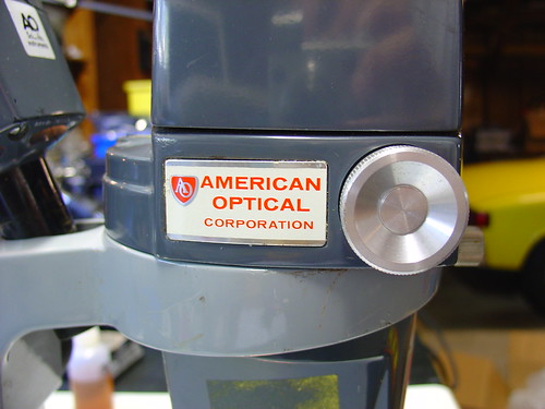
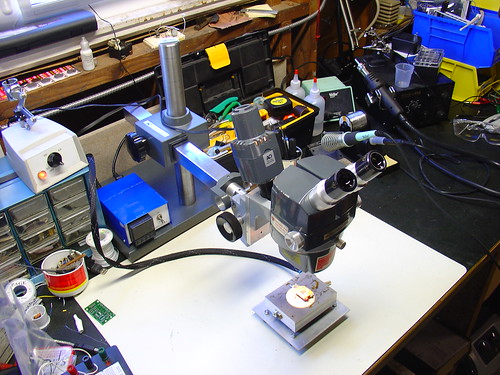
In January of this year, I scored a stereo zoom microscope on eBay.  While my scope is far from state of the art (it’s a “vintage” American Optical model 569) the optics are fantastic and it quickly became the most prized piece of equipment in my shop.  Here’s a photo of the scope shortly after I added it to my lab, for more photos and information about it, see my original post.

Stereo Zoom Microscope

For the first few months, I used the scope pretty much as it arrived.  One of the first major tasks I used it for was assembling the first batch of AVR HV Rescue Shields, and for this purpose it worked extremely well.  However, as time went on, it became clear that I needed to improve my setup in a couple areas:

  1. The magnification range of 7-30X was great for working on a few tightly grouped 0805 or smaller components, but was too high for general PCB work.  A typical BGA package was larger than the field of view.
  2. The included incandescent projector-style illuminator (shown piggybacked on the scope in the photo above) could only be placed in a limited set of positions and did not have adjustable focus – it made a nice, bright spot in the center of the image that didn’t fully illuminate the field at low zoom levels.  While it is removable from the scope (this provides a workaround for these issues), the included stand took up too much bench space to be practical.

Upgrading the microscope:

The first upgrade I made was to add a secondary objective aka barlow lens to the scope.  A secondary objective serves to increase or decrease the total magnification of a microscope, while simultaneously trading off working distance, the distance between the bottom of the microscope and an object in focus on the bench.  In my case, I added a 0.5x secondary objective, which gave me half the magnification while increasing my working distance by approximately 2x.  While American Optical stopped making accessories for the StereoStar 569 long ago, Reichert, who acquired AO’s microscope line, still sells parts and accesories, including the #575 0.5X secondary objective, shown below.

Supplementary Objective

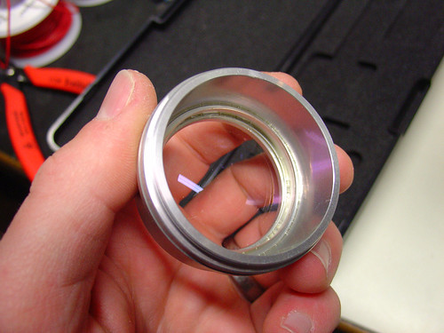
The secondary objective screws into the existing threads on the bottom of the microscope.  Here it is installed on my scope:

Secondary objective installed

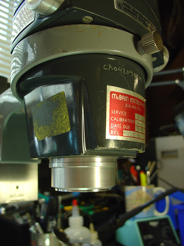
Now with the secondary objective installed, I have a zoom range of 3.5-15X and a working distance of 6-8″.  If I need higher magnification, I can always remove the lens.  Perfect!

The second upgrade I made was to add a fluorescent ring light to the scope.  I picked up the cheapest one I could find on eBay.  This model is sold by Amscope, outputs 8W, and is available for under $30:

Fluorescent ring light

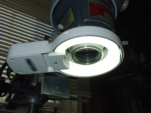
The ring light conveniently attaches to the newly installed secondary objective by tightening three thumbscrews, and provides a decent amount of light that fully illuminates both the object I’m working on as well as the surrounding workbench area, which has been surprisingly helpful.   Best of all, the new light stays out of the way and provides more even illumination than the halogen projector that came with the scope.

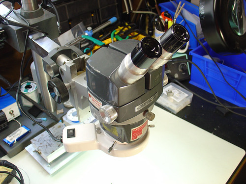
Here’s a photo of the microscope setup as it looks today:

New microscope illuminator setup

Conclusion:

While the changes I made are significant improvements over my original setup, I have made a few observations that may lead to even more tweaks and upgrades in the future:

  • The increase in working distance due to the 0.5x secondary objective is great, but it puts the scope significantly higher above the bench.  I didn’t appreciate that this could be an issue until I had to buy a taller lab chair to see through the eyepieces!  I’m not sure how to work around this, but it’s good to be aware that more working distance isn’t always a good thing.
  • The color temperature of the fluorescent ring light is very poor (cool) compared to the halogen illuminator it replaced.  This gives everything a slightly depressing blue cast and is far from a true color representation.  Most noticeable are tantalum caps, which go from bright orange in color to a sort of slightly orange-ish dark grey under the scope.  Yuck!
  • Ring lights can create pretty nasty glare.  This might be a side effect of how I have the ring light mounted or the distance to the bench.
  • The 8W fluorescent lamp is ok, but more light would be better.  Fluorescent ring lights are nice and cheap, but better performance can be achieved with a significantly more expensive fiber optic illuminator.  I may look into getting one of these in the future.

Despite these minor issues, I am pretty happy overall with the new setup even after a couple hundred hours of heavy use.

New Stereo Zoom Microscope for my Electronics Lab!

Soldering surface mount (SMT) components is tricky, particularly if you can’t see what you are doing due to the small scale of most SMT parts.  Since I started working with SMTs at home I have suffered with a 10x magnifier ring-light.  It works, but it’s tricky to use, mainly because the working distance is so small that getting a soldering iron on a part and keeping that part in focus are almost mutually exclusive.

The right tool for this job is a stereo microscope.  Stereo microscopes use two separate optical paths to provide you with depth perception, very helpful for working with 3-dimensional objects like printed circuit boards.  Even better is a stereo zoom microscope, where the magnification factor can be changed by turning a knob instead of swapping out lenses.

Until now I assumed that a stereo zoom microscope would be way out of my price range, at least several hundred or a thousand dollars for a very basic setup.  However, some searching on eBay showed that good deals can be had, and a used microscope with a boom stand suitable for surface mount work can be found for as little as $200-$300.  New microscopes are available for $400-$500, although there is some debate regarding the quality of low-cost imported microscopes.  Caveat emptor.

For surface mount soldering, 7-30x magnification is reasonable (that’s 10x eyepieces * a 0.7-3x objective), and a 4″ or greater working distance makes using tools under the microscope a lot easier.

I ended up buying an American Optical (AO) model 569 with an illuminator and boom stand, shown below.  Total cost was just over $200 with shipping.

Stereo Zoom Microscope

Combined with the PID controlled hotplate I just put together this is a very powerful setup for doing rework of very tiny components – I could probably work with 0402’s, maybe even 0201’s if I was careful.  Using this setup, 0805’s are easy. (and they look huge!)

The scope is very old, it was made in the late 1970s, but it has survived in extremely good condition.  Upon receiving it, I tightened some setscrews and regreased the slides and it’s as good as new, despite being over 30 years old!

American Optical Corporation

There are a few more photos of the microscope setup on flickr.

The image quality is excellent.  Here are a couple pictures of my SYBA USB-Audio Adapter taken with the microscope and my Sony DSC-V1 digital camera.  I held the camera up to one eyepiece, set it into macro mode, and snapped the shutter – these images are straight off the camera with no retouching.

Microscope images of the SYBA USB-Audio Adapter Microscope images of the SYBA USB-Audio Adapter

DIY PID Controlled Soldering Hotplate

PID Controlled Hotplate

In preparation for my Arduino-based AVR HV Programmer boards coming back, I decided to step up my home lab surface mount soldering capabilities.

Step one was to find a cheap stereo zoom microscope on ebay, with 7-32X magnification, perfect for working on surface mount devices.  One of my biggest frustrations in the past is that with a cheap magnifying ring light, I can’t actually see what I’m working on – not any more!  I’ll post some photos of the microscope when it comes.

Step two was to build a soldering hotplate.  I like using a hotplate for surface mount soldering because you can actually watch the board as the solder paste reflows, and manually add/remove/nudge components around with a set of tweezers.  This is great for engineering work where you may still be making component changes and other tweaks to the board.  Mass production is probably best left to a reflow (aka toaster) oven.

I posted a few photos of the hotplate on flickr, which ended up on Hackaday.

The hotplate:

PID Controlled Hotplate

The heater is a 1/2″ 500W, 120VAC cartridge heater I bought from McMaster-Carr for about $25.  The hotplate itself is a 3x4x1″ chunk of aluminum that I machined with a carefully sized hole just below the center for the heater to slip into, as shown.  A type-K thermocouple (top right) measures the temperature and provides a signal to the controller.  Ceramic standoffs insulate the hotplate from the bottom aluminum baseplate.  For safety, there is also a ground strap, shown on the bottom right.

This the second PID controlled project I have done, the first was my PID Controlled Solder Paste Fridge.

The controller:

PID Controlled Hotplate

The controller box contains an Omega CN77000 series PID controller and an IR/Crydom 240V 40A (overkill!) D2440 Solid State Relay (SSR), along with a power switch, fuse, and power connector.  The PID controller and solid state relay were both found at a now-defunct Silicon Valley surplus store for a few bucks each.  A 3′ umbilical cable connects the controller to the hotplate.

60/40 leaded solder reflows at about 185C, and lead-free solder is around 200-230C depending on the alloy.  (Wikipedia has a good list of reflow temperatures.)  The hotplate can easily reach these within a minute or two from room temperature and could get much hotter if necessary.

It can also be used to cure epoxy and perform any other tasks that require a precisely controlled heater – this could be the world’s most overengineered coffee warmer, if not for the dangers of lead poisioning.

Update: I just posted some more information about the microscope.