The amplifier was designed with an early version of Agilent ADS, PCBs were fabricated on Rogers 5880 (Duroid), and we hand built several prototypes on K-connector fixtures that Tony designed. Measured results were consistent with our simulations.
Tony and I won an award for this project at the Eureka! undergraduate research conference in June 2000.
I heard recently that this project is being used as an example of a good EE senior design project at other universities, so I dug up an original copy of the paper we submitted and posted a PDF here.
Welcome to Part 3 of the Diamond Chop Saw build. In this installment I’m going to focus on the construction of the mechanical aspects of the saw structure, motor attachment, vacuum chuck, and splash guard. This is a picture-heavy entry…
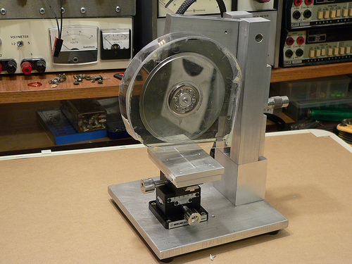
After thinking for a while about how to build the saw, I decided that it would be best to have the blade move only in the vertical axis, and the workpiece move horizontally in two axes. This led to the overall machine design which consists of a vertical column with pivoting cutting head assembly, and a workpiece holder that has two axes of horizontal motion.
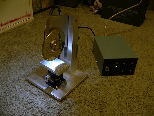
Completed Dicing Saw
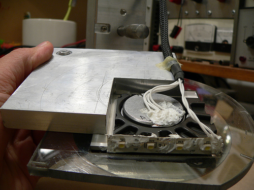
I wanted to ensure the motor and blade had a rigid, heavy mounting structure to reduce effects of vibration and flex on cutting performance. I decided to mount the motor using the original mounting flange from the hard drive enclosure since it was nicely machined to match the motor flange. I used a hacksaw to cut out the shape roughly to size, then straightened up the edges and machined a mounting recess on my milling machine. The L-shaped piece of aluminum is 1/2 inch thick which gives lots of weight and provides sufficient thickness for mounting the bearing while preventing motion orthogonal to the bearing axis.
Cutting Head Assembly
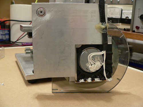
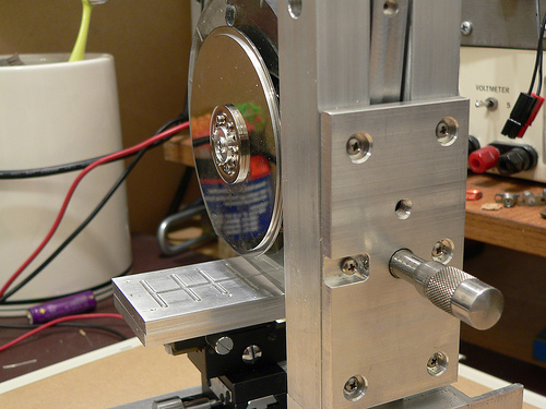
Another view of the cutting head assembly. In the upper left hand corner is the pivot bearing. The bearing is held in place with a set screw that goes through the L-shaped aluminum piece. Along the bottom edge of the black hard drive enclosure portion I attached a strip of white LEDs to help light the work area. RTV Siliconeis used to seal the electrical contacts from water that migt not be caught by the splash shield. At the lower left hand corner of the aluminum plate is a rounded off screw. The cutting depth adjustment micrometer pushes against this rounded off screw. Pushing against the aluminum would be less accurate (aluminum would become unevenly worn).
Cutting head assembly (rear view)
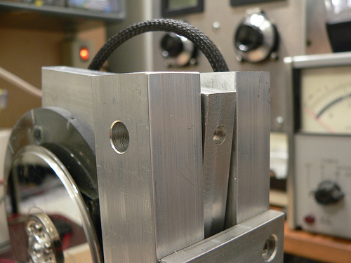
At the top of the column on either side is a hole for the screws that hold the pivot bearing (also from a hard drive) in place. Luckily the one I used has 4-40 threaded holes on either side. A screw on each column holds the bearing in place, and then the rest of the column assembly and adjustment plate are attached resulting in a good alignment of the column to the bearing.
Pivot bearing/column mounting detail
Controlling the depth of the cut is critical, as my cuts will be as small as 5 thousandths of an inch deep! I mounted a micrometer head to a plate on the back of the column which controls the height of the cutting head assembly.
Rear view of the column and depth adjustment control
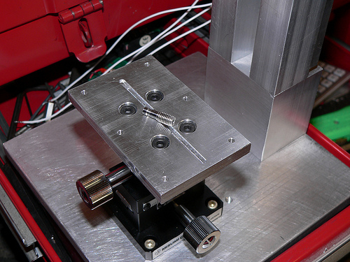
Now for a little detail on the vacuum chuck… The chuck is made from two 1/4 inch plates of aluminum. The top surface has a shallow set of trenches cut to distribute the suction across the bottom surface of the glass plate used for holding parts. The lower plate has a deep trench cut in it to distribute the suction to the three small holes drilled on the top plate. The whole thing is held together with screws and sealed with silicone. I made a set of hose barbs (one is pictured below) so that I can use 1/8 inch vinyl tubing to connect to my vacuum pump. The barbs were made by turning down 10-32 stainless steel screws on my lathe.
Lower half of vacuum chuck with custom-made hose barb
The last major component of the saw is the splash guard. This actually took a fair amount of effort to make, as I broke pieces more than once and had to start over. Essentially it is a two-piece design with a thick piece screwed to the cutting head assembly, and a thinner piece which screws onto the first. I used a heat gun to soften the plastic and carefully mold it to the shape of the face plates. I then glued the curved section and the outer face plate together using epoxy and while not very pretty, it holds together well.
Splash guard on the saw
That pretty much sums up the mechanical aspects of the saw construction. Next week I’ll post the 4th and final installment which will include alignment and attachment of the blade, and actual use of the saw!
This is guest blogger Tony reporting on my latest project, a very small, precise circular chop saw. Why would anyone want to build such a saw you might ask? Well, to make parts for another project of course!
So here’s the background….I’m building a ham radio that operates at 47 GHz. At such a high frequency there are very few components that can be soldered on to circuit boards, let alone components that even come packaged! The easiest way to build a high performance radio at these frequencies is to use MMICs (Monolithic Microwave Integrated Circuits). These are really just fancy, yet fairly simple circuits made from exotic materials, most commonly Gallium Arsenide (GaAs) instead of the usual Silicon used for normal chips. Before MMICs were in widespread use, individual transistors had to be used, requiring delicate and hard to make external matching elements. MMICs are like nice little 50 ohm building blocks. Low Noise Amplifiers (LNAs), mixers, Power Amplifiers (PAs), phase shifters, etc. etc. are all available in this form. Trouble is that you have to connect these pieces up to make a functional radio (or at least the microwave portion of it).
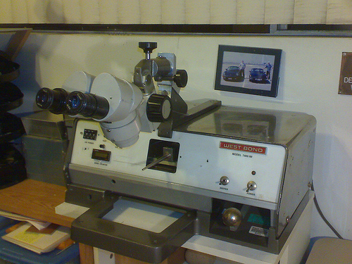
My WestBond wedge bonder
Wire bonding is the usual method for connection and is really just a method of welding a wire (or ribbon) from one chip to the next. It turns out that you actually need space in between the chips, for thermal reasons, RF reasons, and for placing the requisite bypass capacitors. So what goes in between the chips? Well, coax cable is pretty much out, and most common circuit board materials start getting pretty lossy at 10+ GHz, and even the good stuff (PTFE-based usually) starts getting kinda lousy at 40+ GHz. At very high frequencies, materials like ceramics and quartz become worthwhile. In my radio I chose to use pre-made alumina ceramic substrates (tiny circuit boards). These come with a gold layer on the back, and a gold line on top etched to perform as a 50 ohm transmission line (just like coax and just what the MMICs want to see). I bought these with a number of other hams last year in a group buy. They are fairly expensive being that they are 5 and 10 mils thick!
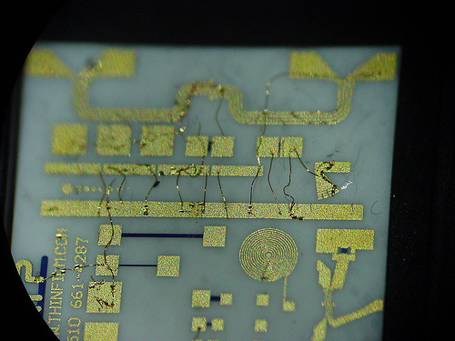
My first test bonds on an alumina ceramic substrate (ugly)
To make the best use of the sections that I bought I decided I needed to cut them to length. Well how do I do that? The thickest pieces are 10 mils thick (a piece of printer paper is 4 mils thick) and they are brittle! Beyond cutting, how do I hold the piece while cutting and when it’s done? The resulting pieces may be just 100 mils long, and 50 mils wide. Obviously a pair of vice-grips simply won’t do.
So my first thought was a Dremel tool and tape. This method could work, but it does not lend itself well to making measured cuts. At 47 GHz, a few hundredths of an inch is a lot! Also, the available diamond blades for dremel tools are fairly wide and I wanted to waste as little of the small substrates as possible. At this point I made a lucky find on eBay.
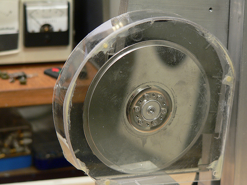
In the semiconductor industry, one of the last steps of making a chip is called “wafer dicing.” After a wafer full of chips is made, they need to be cut out into individual parts. To do this, wafer dicing machines were developed. These are CNC saws that use a high speed (as high as 60,000 rpm) air bearing spindles with diamond abrasive blades. They can cut lines across large dinner plate sized wafers that are as narrow as only a few tens of microns. Luckily there is enough wafer dicing going on in the world that there is a source of surplus blades on eBay. Not all blades are well suited for all materials, so do some research if you are interested. Disco (a Japanese company) is one of the largest dicing blade manufacturers.
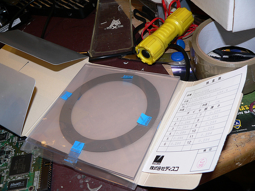
Large (4.6 inch diameter) wafer dicing blade in it's packaging.
While reading the last paragraph you may have spotted a few words indicating unobtanium. Those words are “high speed air bearing spindle.” Well I chose to use a hard drive motor instead, because they have excellent bearings and are readily availble for free. While they don’t move as fast, I don’t care. I have a few short cuts to make, not millions of chips.
So that is an introduction to what I’m doing. For the most part the saw has been built using surplus parts and remnant pieces of metal from my favorite local metal supply house M&K Metals in lovely Gardena, CA. As of this entry, the saw is nearly complete, all that is left is the splash guards. I’ll be posting the build of this project in several parts, so stay tuned.
And a link to my Flickr photo set for this project: Dicing saw
Ed. note:This is a guest post by a good friend of mine, Tony Long, KC6QHP. Hopefully Tony will be contributing more to the blog in the future and we’ll get to see some of the interesting things he’s working on in his lab in SoCal. Let’s all welcome Tony to the blog! – Jeff
By 1995 I had been a licensed ‘ham’ for 4 years. I was in the 11th grade and interested in a putting together a far-out science fair project. Over the next two years I worked with two hams, mentors, and friends to get the project done. One of them was Chuck Houghton, WB6IGP. He and Kerry Banke N6IZW started the San Diego Microwave Group back in the 1980’s. What they started was an informal group that still meets in the garage at Kerry’s house in La Mesa once a month to talk about and work on microwave ham radio projects. This group has been highly influential in the interests and careers of myself and Jeff. We both went to college in San Diego and attended these meetings and just as importantly, had a great source of parts and articles from Chuck.
Chuck, who was 68, passed away peacefully in his home on April 29th.
Chuck and Kerry started out on the microwave bands by using surplus microwave burglar alarm systems and modifying them for amateur radio use. Chuck was in some ways an early version of many DIY electronics bloggers of today. He not only did experiments, and built interesting projects, he wrote about them, told others how to do it, and supplied printed circuit boards, kits of parts, and so on. He wrote a monthly column in 73 magazine and later in CQ-VHF detailing his experiments. His reach was worldwide, and no doubt has enabled the microwave amaetur radio hobby to flourish.
So, to Chuck I bid a farewell and 73. You will be missed but you will be remembered well!