Dealextreme is home to a few good buys on electronics prototyping supplies.
Here are a few of my favorites.
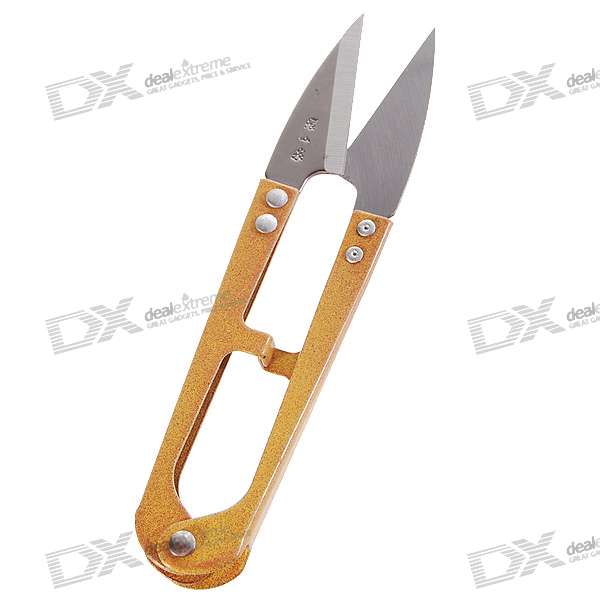
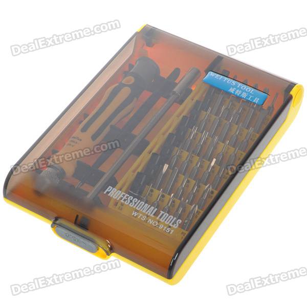
Thrum scissors
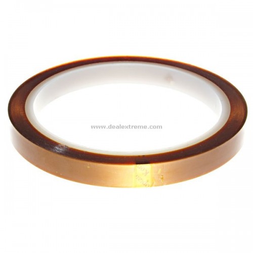
These miniature thrum scissors are handy for opening ESD bags, trimming the ends off of SMD component reels, and cutting kapton tape, among other things. I keep several pairs at work and at home and use them all the time. They are much more precise than standard scissors and good for all sorts of light duty applications. (You can also buy these from amazon.com here: Blue Handle Stitching Yarn Thrum Scissor Tool 3 Pcs)
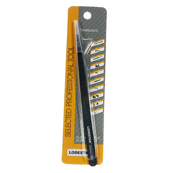
ESD Tweezers
These Lodestar L601110 ESD tweezers are perfect for all sorts of electronics prototyping and repair work. I find them very useful for surface mount assembly and rework, but I also use them for precision gluing, discharging SMD caps, shorting traces on PCBs, and also sorts of other off-label uses. They are cheap enough that when I bend or otherwise damage one set, I’ll throw them away and buy another. If I only owned one pair of tweezers, it would be these.
Finally, I bring you the conclusion of my Diamond Chop Saw series!
In this part I’ll cover a few remaining issues, but mostly I’ll report on my use of the machine in the construction of my 47 GHz radio, for which this project was intended. If you’re not already familiar with this project, you might want to go back and start by reading Part 1.
Attaching/Aligning the Blade
Attachment of the blade to the hard disk platters (see part 2) sets the basic accuracy of the tool. If the blade is out of plane the cut will be wider than the blade. If the blade is off center, portions of the blade will wear faster. Achieving perfection is virtually impossible, but I managed to get a ‘good enough’ result.
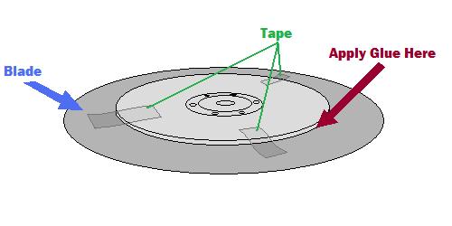
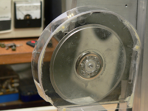
My method was to lay the ring blade down onto the larger platter and use tape to temporarily hold the blade in place while I manually spun it around to check for centering.
Method for centering the blade
A little fiddling and re-alignment will get things pretty close. After the centering is good, the next step is to glue the blade into place. I used tiny drops of Zap-a-Gap around the inner edge of the ring and held the two together firmly as the glue set.
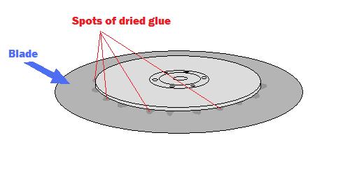
After gluding the blade, spots of glue are visible on the top surface
The result is not perfect, but cuts I have done seem to be sufficiently narrow.
The Cutting Setup
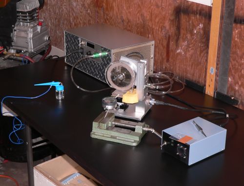
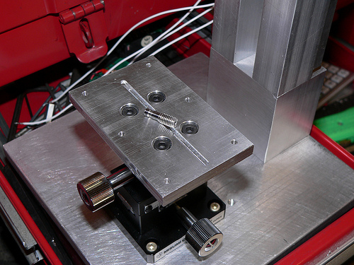
The picture below shows the setup for making cuts. The large silver box in the background is the vacuum pump, the green vise in front is holding a digital indicator (for making precisely measured cuts) and the blue airbrush is ready for spraying water onto the cutting surface.
Dicing saw setup
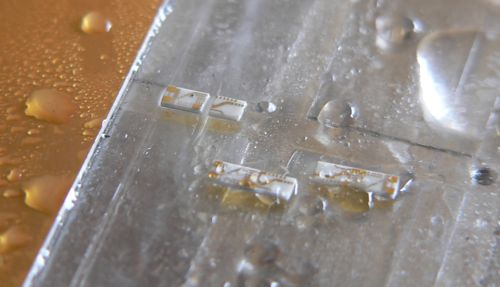
The parts to be cut are mounted on glass slides using Crystalbond adhesive, a thermoplastic mounting polymer.
Test substrates about to be cut
Using the Chop Saw
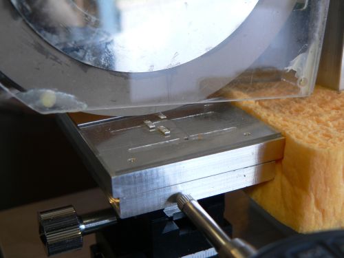
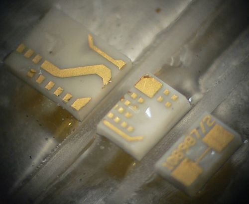
Below are some pictures of cuts made with the saw.
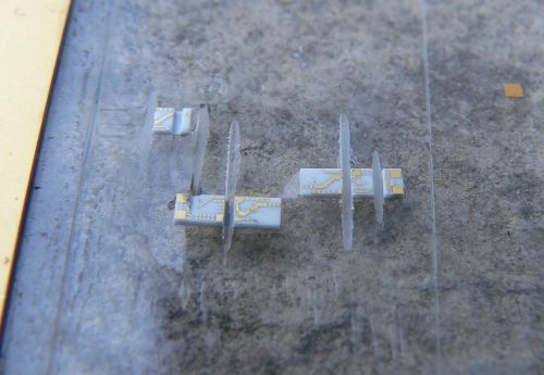
A partial cut through one of the substratesSeveral diced pieces. Microscope view of a part diced into three pieces
From the photos above it is clear that the saw is working reasonably well. The cuts are straight, the pieces have no obvious large chunks missing, and the gold metallization shows minimal signs of peeling. I have made many cuts using this saw including angled cuts. I have also used the saw to carefully strip off the backside metallization. This will come in handy when I am making diveboard-style waveguide transitions. I have also used the X/Y table to feed the piece along the blade, allowing me to make much longer cuts than in “chop” mode. These came out very nicely as well.
The accuracy of the saw is reasonably good. Using a dial or digital indicator, cuts can easily be made with 0.001 inch accuracy, which is sufficient for circuits working through 50 GHz at least.
One issue that was of concern initially was whether a hard drive motor actually had enough power to do the job. It turns out the motor works fine as long as the cuts are made slowly. Fast cuts are not advisable anyway, as the part is more likely to fly off into oblivion. Some of the substrates I cut had fairly thick metal backing and required slower cuts.
Future Improvements
Every project ends up with room for improvement. With this project a few things come to mind including a precision machined spindle with a better mounting mechanism. This would require a much larger lathe than what I own, and some careful though into balancing. Another improvement would be a self-contained coolant sprayer and vacuum pump for the chuck. Setting up the dicing saw currently requires a vacuum pump, an air compressor, and so on. Another nice feature would be a microscopic camera to observe the cutting in action. And finally a CNC retrofit would be nice. All of these upgrades would be handy, but as it is, the saw is immensely flexible and precise. I’m still on the first blade which is showing no signs of wear.
Conclusion
It has been a lot of fun putting together this series of articles and even more fun putting together and using this saw. So if you are planning on putting together a saw like this, happy cutting! If you are just planning on building something with a hard drive motor, they are really handy for certain applications where high precision, high RPMs, and cheapness are required.
The single biggest challenge to doing “real” SMT work (0805 or smaller components and fine lead pitch ICs) at home is being able to actually see what you are doing. I know that there are many hobbyists (and maybe even some budget-conscious professionals) who will disagree with me, but I wouldn’t dream of working with surface mount components without using a microscope. I’ve tried many alternatives, including a 10X handheld triplet loupe, a magnifier ring light, even a nausea-inducing magnifying visor, and none of these even come close.
In case I haven’t made myself clear: I would rather solder SMT’s with a 150W soldering gun than with anything other than a decent stereo microscope.
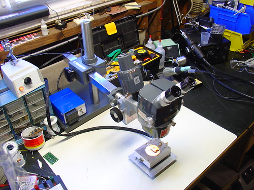
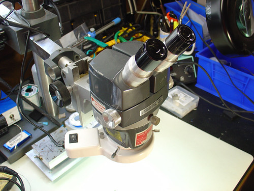
In January of this year, I scored a stereo zoom microscope on eBay. While my scope is far from state of the art (it’s a “vintage” American Optical model 569) the optics are fantastic and it quickly became the most prized piece of equipment in my shop. Here’s a photo of the scope shortly after I added it to my lab, for more photos and information about it, see my original post.
For the first few months, I used the scope pretty much as it arrived. One of the first major tasks I used it for was assembling the first batch of AVR HV Rescue Shields, and for this purpose it worked extremely well. However, as time went on, it became clear that I needed to improve my setup in a couple areas:
The magnification range of 7-30X was great for working on a few tightly grouped 0805 or smaller components, but was too high for general PCB work. A typical BGA package was larger than the field of view.
The included incandescent projector-style illuminator (shown piggybacked on the scope in the photo above) could only be placed in a limited set of positions and did not have adjustable focus – it made a nice, bright spot in the center of the image that didn’t fully illuminate the field at low zoom levels. While it is removable from the scope (this provides a workaround for these issues), the included stand took up too much bench space to be practical.
Upgrading the microscope:
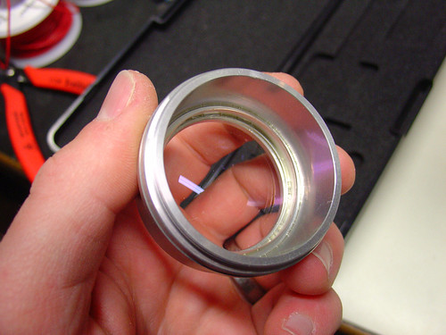
The first upgrade I made was to add a secondary objective aka barlow lens to the scope. A secondary objective serves to increase or decrease the total magnification of a microscope, while simultaneously trading off working distance, the distance between the bottom of the microscope and an object in focus on the bench. In my case, I added a 0.5x secondary objective, which gave me half the magnification while increasing my working distance by approximately 2x. While American Optical stopped making accessories for the StereoStar 569 long ago, Reichert, who acquired AO’s microscope line, still sells parts and accesories, including the #575 0.5X secondary objective, shown below.
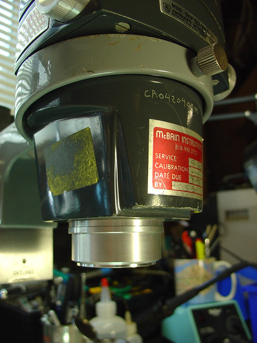
The secondary objective screws into the existing threads on the bottom of the microscope. Here it is installed on my scope:
Now with the secondary objective installed, I have a zoom range of 3.5-15X and a working distance of 6-8″. If I need higher magnification, I can always remove the lens. Perfect!
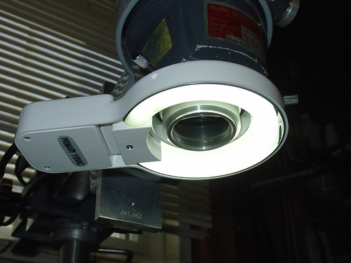
The second upgrade I made was to add a fluorescent ring light to the scope. I picked up the cheapest one I could find on eBay. This model is sold by Amscope, outputs 8W, and is available for under $30:
The ring light conveniently attaches to the newly installed secondary objective by tightening three thumbscrews, and provides a decent amount of light that fully illuminates both the object I’m working on as well as the surrounding workbench area, which has been surprisingly helpful. Best of all, the new light stays out of the way and provides more even illumination than the halogen projector that came with the scope.
Here’s a photo of the microscope setup as it looks today:
Conclusion:
While the changes I made are significant improvements over my original setup, I have made a few observations that may lead to even more tweaks and upgrades in the future:
The increase in working distance due to the 0.5x secondary objective is great, but it puts the scope significantly higher above the bench. I didn’t appreciate that this could be an issue until I had to buy a taller lab chair to see through the eyepieces! I’m not sure how to work around this, but it’s good to be aware that more working distance isn’t always a good thing.
The color temperature of the fluorescent ring light is very poor (cool) compared to the halogen illuminator it replaced. This gives everything a slightly depressing blue cast and is far from a true color representation. Most noticeable are tantalum caps, which go from bright orange in color to a sort of slightly orange-ish dark grey under the scope. Yuck!
Ring lights can create pretty nasty glare. This might be a side effect of how I have the ring light mounted or the distance to the bench.
The 8W fluorescent lamp is ok, but more light would be better. Fluorescent ring lights are nice and cheap, but better performance can be achieved with a significantly more expensive fiber optic illuminator. I may look into getting one of these in the future.
Despite these minor issues, I am pretty happy overall with the new setup even after a couple hundred hours of heavy use.
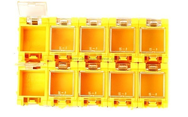
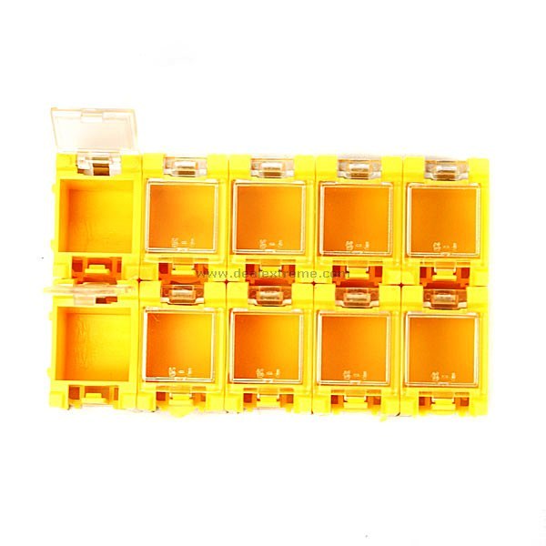
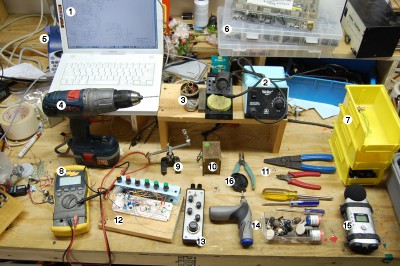
With the exception of the audio recorder and circuit bending tools, pretty much every piece of equipment on that bench can be found on mine as well. I even have the same yellow bins!
There’s a great writeup on his site describing each numbered tool in the photo. If you started from scratch and bought all of the items on his list, you would have a great instant electronics workshop.
Welcome to Part 3 of the Diamond Chop Saw build. In this installment I’m going to focus on the construction of the mechanical aspects of the saw structure, motor attachment, vacuum chuck, and splash guard. This is a picture-heavy entry…
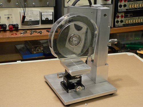
After thinking for a while about how to build the saw, I decided that it would be best to have the blade move only in the vertical axis, and the workpiece move horizontally in two axes. This led to the overall machine design which consists of a vertical column with pivoting cutting head assembly, and a workpiece holder that has two axes of horizontal motion.
Completed Dicing Saw
I wanted to ensure the motor and blade had a rigid, heavy mounting structure to reduce effects of vibration and flex on cutting performance. I decided to mount the motor using the original mounting flange from the hard drive enclosure since it was nicely machined to match the motor flange. I used a hacksaw to cut out the shape roughly to size, then straightened up the edges and machined a mounting recess on my milling machine. The L-shaped piece of aluminum is 1/2 inch thick which gives lots of weight and provides sufficient thickness for mounting the bearing while preventing motion orthogonal to the bearing axis.
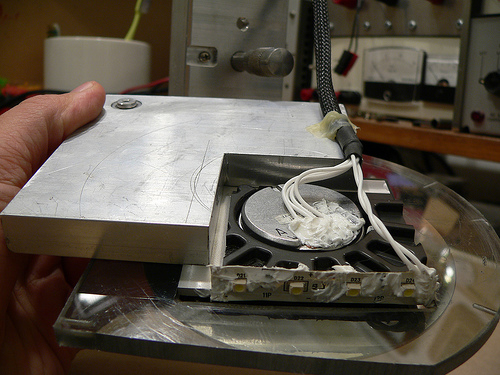
Cutting Head Assembly
Another view of the cutting head assembly. In the upper left hand corner is the pivot bearing. The bearing is held in place with a set screw that goes through the L-shaped aluminum piece. Along the bottom edge of the black hard drive enclosure portion I attached a strip of white LEDs to help light the work area. RTV Siliconeis used to seal the electrical contacts from water that migt not be caught by the splash shield. At the lower left hand corner of the aluminum plate is a rounded off screw. The cutting depth adjustment micrometer pushes against this rounded off screw. Pushing against the aluminum would be less accurate (aluminum would become unevenly worn).
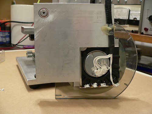
Cutting head assembly (rear view)
At the top of the column on either side is a hole for the screws that hold the pivot bearing (also from a hard drive) in place. Luckily the one I used has 4-40 threaded holes on either side. A screw on each column holds the bearing in place, and then the rest of the column assembly and adjustment plate are attached resulting in a good alignment of the column to the bearing.
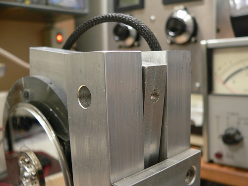
Pivot bearing/column mounting detail
Controlling the depth of the cut is critical, as my cuts will be as small as 5 thousandths of an inch deep! I mounted a micrometer head to a plate on the back of the column which controls the height of the cutting head assembly.
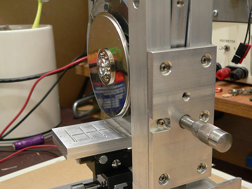
Rear view of the column and depth adjustment control
Now for a little detail on the vacuum chuck… The chuck is made from two 1/4 inch plates of aluminum. The top surface has a shallow set of trenches cut to distribute the suction across the bottom surface of the glass plate used for holding parts. The lower plate has a deep trench cut in it to distribute the suction to the three small holes drilled on the top plate. The whole thing is held together with screws and sealed with silicone. I made a set of hose barbs (one is pictured below) so that I can use 1/8 inch vinyl tubing to connect to my vacuum pump. The barbs were made by turning down 10-32 stainless steel screws on my lathe.
Lower half of vacuum chuck with custom-made hose barb
The last major component of the saw is the splash guard. This actually took a fair amount of effort to make, as I broke pieces more than once and had to start over. Essentially it is a two-piece design with a thick piece screwed to the cutting head assembly, and a thinner piece which screws onto the first. I used a heat gun to soften the plastic and carefully mold it to the shape of the face plates. I then glued the curved section and the outer face plate together using epoxy and while not very pretty, it holds together well.
Splash guard on the saw
That pretty much sums up the mechanical aspects of the saw construction. Next week I’ll post the 4th and final installment which will include alignment and attachment of the blade, and actual use of the saw!