Where is the header pinout diagram
Posted: Wed Nov 23, 2016 4:37 pm
Hi,
Just put together my kit. Seems to be working.
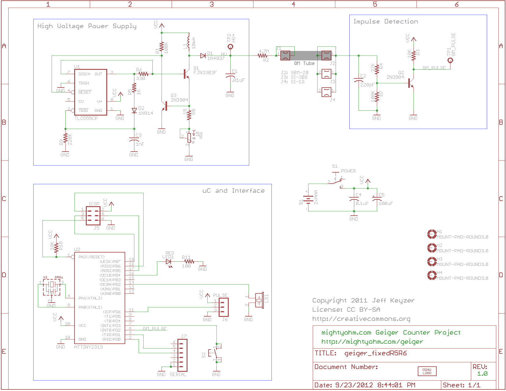
Where can I find a diagram of the header pinout? The PULSE, ICSP, and SERIAL header pins. Where is there any documentation on which pin does what and where they are located.
I've searched around this forum but have not found any simple info on how these work. For example, the docs show the PULSE outputs as a 3v, gnd, and signal but doesn't show which is which.
Any help would be appreciated. I just want to count clicks from the pulse output.
Just put together my kit. Seems to be working.
Where can I find a diagram of the header pinout? The PULSE, ICSP, and SERIAL header pins. Where is there any documentation on which pin does what and where they are located.
I've searched around this forum but have not found any simple info on how these work. For example, the docs show the PULSE outputs as a 3v, gnd, and signal but doesn't show which is which.
Any help would be appreciated. I just want to count clicks from the pulse output.