
This is the third part of an ongoing series about building a low cost, open source streaming internet radio. If you haven’t already, check out part one and part two for some background about the project.
Hacking the Asus WL-520GU Wireless Router:
In the last part of this series, I selected the Asus WL-520GU wireless router as a suitable embedded platform for my Wifi Radio project. I have since posted some detailed specs on this impressive low-cost router, revealing it’s powerful Broadcom BCM5354 core, 4MB flash, and 16MB SRAM. Granted, there are many more powerful routers out there that have USB support, will run Linux in various forms, and have built-in WiFi. However, the WL-520GU does almost everything we need to build a streaming internet radio and costs under $50 (I have seen them for as little as $26 after rebate), which is very impressive indeed.
To convert this router into a powerful embedded system, we need to make a couple modifications. First, we need to throw out the stock firmware. It turns out that this router, like many others, runs Linux from the factory. However, because it was designed to be a wireless router and not much else, the stock firmware doesn’t include a very wide set of features (and certainly was not intended to be accessed by the customer). Thankfully, there are several open source Linux distributions available that support this router, including my favorite, OpenWrt. In addition, Asus has made it fairly straightforward replace the stock firmware with our own custom Linux build which can include all the programs, drivers, and utilities we can cram into 4MB of flash.
Warning:
Before we start hacking the router, there are a couple things I should mention:
- From this point onward, your warranty is toast. Don’t even THINK about trying to send a modified router back to Asus for warranty service. In the end it hurts people like us, because Asus will try to make it harder for people to perform the same modifications in future products.
- You may inadvertently destroy your router. If you are not comfortable with the fact that a misstep during the reflash or a stray solder bridge could ruin your hardware, stop now. Sorry. If you really take a wrong turn, you could damage your PC as well, but this is extremely unlikely. If you do somehow damage your router or PC doing these modifications, I assume no responsibility for any damages!
This tutorial assumes that you have already established the router is basically working by assembling it, plugging it in and checking for it’s wireless signal and internal webserver. The user manual does a good job of leading you through this process, but don’t use the supplied CD – follow the advanced/manual instructions instead.
Accessing the internal serial port:
The OpenWrt install will be easier if we can find a way to access the internal serial port of the router. The built-in serial port gives us a way to view Linux boot and status messages and get shell access as well. The serial port will also come in handy later when we want to add a user interface to the radio.
You will need:
- A desktop or laptop computer with an open USB and Ethernet port.
- Your shiny new ASUS WL-520GU wireless router (R1.02)
- A strip of breakaway 0.1″ male header
- A FTDI-232-3V3 USB to serial adapter cable ($20 @ Adafruit) or some other means of connecting a 3.3V level serial port to your PC
- A small scrap of perfboard and a strip of female 0.1″ header (not strictly necessary, see below)
-and-
- A basic electronics workbench with ample light, a temperature controlled soldering iron, a solder sucker, solderbraid, wirecutters, and pliers. Servo Magazine recently held a contest to see who could build the best electronics workbench for under $100, the results should be helpful for anyone just starting out. If you’re uncomfortable soldering, find someone else to help you with this part at your local hackerspace.
Step 1 – Open the router
Remove the power cord and antenna (the base unscrews). Flip the router over and look at the bottom. You should see something like this:
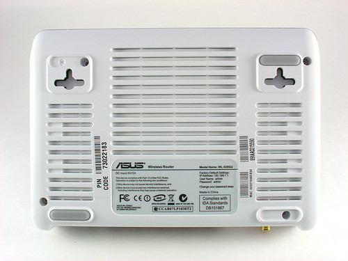
Note there are four screws that hold the router together, two are hidden underneath the rubber feet. The feet are stuck on really well, but persistent prying with a fingernail will get them off eventually. Remove the four screws and set them aside. The top cover should come off without too much trouble.
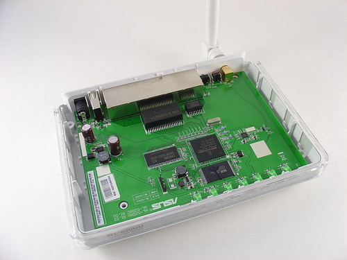
Now that the router is open, you should see something like this:
Step 2 – Add a serial port header
Remove the PCB from the plastic enclosure by gently pulling it up and towards you (ethernet ports facing away).
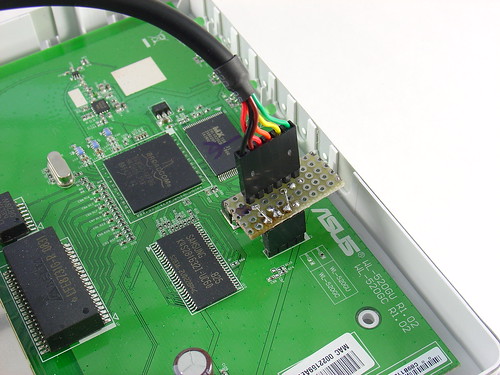
Just to the left of the ASUS logo in the photo below, you will see a 4-pin header that I have installed to access the internal serial port of the router, the router ships without this header. Instead, you will see four solder filled vias in a row in the same spot.
You will need to use your soldering iron and a solder sucker to remove most of the solder so that the header can be installed. A higher power soldering iron will help with removing solder from the first via on the left (mine is a 60W Weller WTCPT). This via connects to a ground plane which sucks heat away from the iron and makes the job more difficult. Be patient and persistent and you should be able to wick any remaining solder away with some soldering braid if necessary.
Break a 4-pin chunk of male header off the strip. Pop the header into the board and carefully solder it into place. If it doesn’t fit, chances are there is still some solder left in the vias. You should end up with something like this:
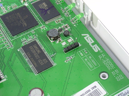
The pin functions are, from left to right in the photo:
GND TX RX 3.3V
Step 3 – Connect your PC
The FTDI-232-3V3 USB to serial adapter cable provides a handy way to add a 3.3V TTL level serial port to a PC or laptop. The cable has a flat connector on the serial end that can plug directly onto 0.1″ male headers like the one we are using on the router. Unfortunately, the pinout of the FTDI cable (given in the datasheet) does not match that of the router. To resolve this, you have two options:
- Use a tiny screwdriver to pull out the pins from the housing at the cable and rearrange them. Do not connect anything to the 3.3V pin on the router, and swap the TX/RX so that the TX on the router feeds RX on the cable, and vice-versa. Don’t forget to connect the grounds! The downside of this is that now you can’t use the FTDI cable for things like the Boarduino without swapping the pins back.
-or-
- Fabricate an adapter board using a small piece of perfboard and some headers, shown below (click for a larger version):
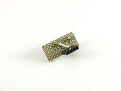
Here is a schematic of the adapter board:

Shown here are the cable and adapter installed on the router. Make sure the ground side of the cable is connected to the pin on the header that is opposite from the fat angled trace (the 3.3V line). Ground is the black wire, on my adapter I marked this with a black dot so I won’t forget and plug it in backwards.
Step 4 – Test the connection
Plug the cable into your PC (you may need some drivers) and open your favorite terminal program. (I like Zterm for the Mac or Hyperterminal on the PC.) Using the terminal program, open the serial port corresponding to the FTDI cable (something like usbserial-FTDQ23LB on the Mac or COM3 on the PC, but your setup may be different.) Set the port options to 115200 baud, 8N1.
Connect the antenna and power supply to the router and plug it in. You should see something like this appear in your terminal program:
Decompressing..........doneCFE version 1.0.37 for BCM947XX (32bit,SP,LE)Build Date: Thu Mar 6 10:05:04 CST 2008 (root@localhost.localdomain)Copyright (C) 2000,2001,2002,2003 Broadcom Corporation.Initializing ArenaInitializing Devices.Boot partition size = 131072(0x20000)et0: Broadcom BCM47xx 10/100 Mbps Ethernet Controller 4.130.31.0Total memory: 16384 KBytesCPU type 0x29029: 240MHz ...
If you do, congratulations, your serial port is working!
The lines that scroll by are boot messages from the Linux kernel of the stock firmware on the router. These messages give you a lot of information about the hardware in addition to information about the operating system and software drivers. Here is a complete transcript of the boot log from my router. If you wait a couple minutes for the router to finish booting and hit enter, you should see a command prompt. From here you can explore and play around with the stock firmware, there is really not much to do here until we reflash the router with OpenWrt.
That’s it for part three. In part four, I’ll talk about installing OpenWrt and connecting the router to your wireless network.
Update: Part four is now available.
Update 2: There is a new Wifi Radio Discussion Forum, hop over there to ask questions about the project or see what other people are working on! (4/12/09)
This might be obvious, but… you need to hit enter to see the prompt.
Other reasons it might not be working… The TX line to the router is not connected. I can’t think of much else.
OK, I am back to being an idiot. Have it connected to a second laptop to put OPENWRT on it, and same problem, can’t hit enter to get to the # prompt:
I have my header and cables all working, and my connection to the PC via hyperterminal shows me the boot up of the router, very cool. The problem is I get only to the next to the last point in your log of the boot, that is, the last thing I see on the hyperterminal screen is this:
echo for PaN ::: &&&PaN
I never get the # prompt. What the heck am I doing wrong….I have the settings on hyperterminal set to 115200 baud, 8N1, but I have other settings I am guessing at, such as Terminal vs. Windows keys, Emulation, Flow control. Is one of these the culprit maybe? Any help appreciated.
Foo
Rob – I agree, that is a nice way of doing the serial port connection. I checked out your photos, very nice.
Foo – Thanks for figuring that out. I guess my terminal defaulted to no flow control because I don’t remember having to set it, but you are right, no flow control is required for it to work.
AND of course the very next thing I tried worked.
After setting emulation to TTY, that didn’t work, so I changed Flow Control to NONE. That was evidently the magic button.
Thanks anyway, maybe this will help anyone else as clueless on the software as I am.
Foo.
Hey, probably a stupid question, but I ask those all the time…
I have my header and cables all working, and my connection to the PC via hyperterminal shows me the boot up of the router, very cool. The problem is I get only to the next to the last point in your log of the boot, that is, the last thing I see on the hyperterminal screen is this:
echo for PaN ::: &&&PaN
I never get the # prompt. What the heck am I doing wrong….I have the settings on hyperterminal set to 115200 baud, 8N1, but I have other settings I am guessing at, such as Terminal vs. Windows keys, Emulation, Flow control. Is one of these the culprit maybe? Any help appreciated.
Foo
Thanks for the great post. I’ll be spending way too much of my time working with these now. I have tons of ideas of projects for them.
BTW: Those F/F headers are here. I use them and the M/M ones all the time, they’re well worth the money.
I thought I’d share the way I connected to the serial port. Instead if using perfboard and a straight header, I used a right-angle header, female-to-female jumpers from Sparkfun, and a strip of straight header to connect to the FTDI cable. I ran the jumpers under the board and out the mounting hole on he bottom, so I can close the case.
I posted photos here on Flickr. That’ll probably make more sense.
crizo – That is a totally legitimate fix. I do stuff like that all the time. There is this really thin 30 gauge wire you can get to help with fixes like that, it’s called Kynar wire and it’s used for wirewrapping.
liz – Sorry to hear your router is sick! The Broadcom CPU gets warm under normal use so I think that’s ok. 3.3V is a good sign too. I’m not sure what you could have damaged. Did you remove power from the router before soldering in the headers?
Looks like I may have goofed and killed my router. It was working fine until i added the headers. I was pretty careful and didn’t apply heat for more than 3-5 seconds at a time. Now no LEDs light and the router doesn’t appear to boot. I’m seeing 3.3v across the outer pins and the broadcom chip is warm to the touch.
Any ideas? Any obvious things I may have done or damaged? Any traces I could’ve busted while removing the solder? I’ve now de-soldered the 4-pin header and looking at the lines that appear to run into the tx and 3.3v pins.
thanks
I nearly put my router out of it’s misery last night.
At first, I had straight pin headers on the serial port. I later decided to remove those and use a 90 degree header to make room for my LCD display. Apparently the trace on the RX pin broke from the stress, and I spent 2 days trying to determine why I couldn’t receive serial from the AVR.
Last night I discovered the trace was broken, so I hesitantly came up with a fix. I used a magnifier and an xacto knife to scratch some of the solder mask off of the rx trace. Then I soldered a fine wire made from a very thin resistor lead from the trace to the header pin. Instant success! It looked extremely delicate so I covered it with a drop of 5 minute epoxy. I’ll post a picture if I get time…
Hi! I am thinking of adding extra ports to the Asus using the 4-pin USB port that you found. I am going to take apart a USB Hub (the the rotating swivel type) and add an extra port above the reset button.
Just wondering if this port that you used for a serial port is also a standard USB port – though supplying 3.3V.
If I take 5 V from elsewhere can I simply add a USB hub soldered to this point ??
Another trick for getting solder out of through holes is to use a sacrifical 24ga piece of copper wire. Use pliers to hold the wire then heat it up with the soldering iron and pass it through the hole.
Then hold heat to wire through board and pull through with pliers. After a pass or three you’ll get enough solder out to give an opening for a pin.
Can you take a picture? Are the holes in the same location and labeled J4? If they are, you are probably right, Asus has saved you some work.
Hi, i just opened my asus WL 520 GU but i didn’t find see four solder filled vias in a row but 4 open holes. Is this possible? This is might be a problem or i am lucky that i just skipped some difficult soldering? Thanks
Cool! Do you have a pic? I bet an internal CDROM audio cable would work too…
And we’ve achieved case closure, using a 100mm male-female RC servo extension cable for the serial cable hookup. It leaves a nice keyed serial port connector protruding from the left side of the case with the Dark Brown wire as ground. This cable is coded Brown, Red, Orange, most others are Black, Red, White. Total cost for it and its mate that cross wires into the TTL-USB serial cable, just a little over a buck.
Except for that, you wouldn’t know what’s under the hood!
Yep, I’m seeing the possibility of a really bad Asus WL-520GU habit growing here. There are all sorts of possibilities.
Another item that can be used for a serial cable is an RC Servo extension cable. The socketted end fits three of the pins on the on-board serial header, put the black wire on ground. That leaves the 3.3v pin in the open and not likely to be shorted to anything. The pins end of the cable can be extracted by flexing it gently till the two parts of the connector come apart and expose the pins which slide out of the little backing piece. They then can be inserted into the TTL-USB serial connector in the proper order.
It is a great feeling when you see that console log appear in the terminal… that really is a tiny computer inside that router, and it is capable of many things!
Solder sucked, header pins soldered in.
Used a connector consisting of an old three wire cooling fan cord from a processor fan whose sleeve bearing went. Hooked the ttl-usb serial cable to a universal breadboard with wirewrap header pins and did the cross wire there.
Put in a lan cable to the local network.
Fired up GTKTerm, Got gibberish, changed serial port speed and restarted. Boot sign in and press enter and we’re at busybox. Ping local server from busybox.
Cool!
Finding ground and power isn’t too hard. To find ground, you can use a multimeter to check for very low resistance (much less than 1 ohm) between each pin and the ground shell of connectors on the board (usually the outside ring of the power plug is ground) or the ground plane on the circuit board. Vcc is a little harder, in this case I saw a fat trace going from the power supply section of the board to one of the pins. When I checked the voltage I saw that this was a constant 3.3V.
TX and RX are harder. You can try measuring the voltage on those pins to see if the port is 3.3V, 5V, or RS-232. Try hooking them up one way, if you don’t see anything, try swapping the pins and check again.
I also learned a neat trick recently. If you take a piezo element (the bare thin disc kind, without the beeper circuitry) and a 1k series resistor, you can probe around in the circuit for certain signals. If you know that the device is outputting serial data (like during boot) you can keep probing around until you hear a signal that sounds like a modem connection (high pitched screeching noise, like if you picked up the phone during a modem call). That will be the TX line from the router. I’ve tried it and it actually works, although there are a lot of decoys on most circuit boards. Clock signals and data lines will make noises too, but none of them will sound quite like the serial port.
I hope that made sense. Still drinking my morning coffee… 🙂
This may be a bit of a noob question, but how do you figure out which is ground, tx, rx and 3.3?
I have a Zyxel P660 HW 61 which Im trying to modify for the same project.
It already has the pins for the serial cable but I dont know which are which
I see lots of great tips here!
schill – I am a firm believer in your method. It’s a little counter-intuitive, but adding a tiny amount of solder to the joint you are trying to remove solder from works 90% of the time. I think the molten solder brings with it a little bit of flux in addition to the improved heat transfer you mentioned. Both of these things together can make a huge difference.
When I’m soldering anything I almost always put a dab of solder on the tip of the iron before applying the iron to the joint. This really speeds up the process of soldering the joint and keeps the tip clean too.
If you are having trouble desoldering the vias even when using desoldering braid or a solder sucker, try applying a little fresh solder to the vias. It seems to help the heat transfer and makes it easier to melt the solder in the via.
FWIW, the Radioshack 45W desoldering iron (64-2060) on one side of the board and a conventional soldering iron on the other works pretty well w/ lead-free solder.
Steve
Jeff,
Wow, you weren’t kidding about the removing the solder from the first via on the left being a pain. My 15watt rat shack iron barely was able to do the job adequately, but with much gnashing of teeth I finally got the header installed. Building and flashing openwrt was trivial compared to that. Time to invest in some real soldering equipment.
fwiw, I wired mine up using an RS232 shifter from sparkfun that I had lying around and it works like a charm. I can’t wait to get it talking to a display.
Drew
Durin,
You’re right, you can flash the router without a serial port, and all of the steps in part 4 can be completed using telnet instead of the serial console (although you will need to determine the IP address of the router once you attach it to a wireless network). However, I plan on using the serial port later to add a control panel to the router, so eventually you’ll need to add it unless you find another way to interface with the router.
Thanks for the feedback and blind-flash instuctions.
The stock firmware images may take more than 60 secs to burn so be sure and wait at least 2-3 minutes (I’d say 5 to be sure) if you reflash back. OpenWrt is much faster given the smaller size of the image.
Jeff
For users who are afraid of soldering and ruining your warranty, it’s very easy to update the firmware without opening the case!
Download the TRX image Jeff posted on part 4 and save it to your desktop. If you’re using windows, you need to download a TFTP client. Mac and Linux have it built in. connect your computer network port to one of the LAN (not WAN) ports on your router. unplug the router, push in the black RESTORE button and hold it down while plugging the power back in. keep holding it down until the power light on the router blinks slowly.
on your computer, fire up TFTP. type:
> mode image
> mode (just to verify it’s in octect/binary mode)
> put openwrt-brcm-2.4-squashfs.trx
wait a few seconds and it will tell you it’s transferred successfully. close tftp and go make some tea for 60 seconds or so, then unplug and replug the router. wait another 15 seconds or so, then telnet to 192.168.1.1
you should log right in and be at a command prompt!
you can always use this method to change the firmware, so you can restore it to factory if you need to return it for some reason. you’re no longer breaking the warranty and it takes a few minutes to do!
Durin
Man, I can’t wait for this to be done. I am excited to get going on this. Rebate on the router ended yesterday tho.
Foo – I’m not too far ahead of the blog. I have OpenWrt working (hoping to post about how I installed it next week) and I am using mpd to stream music, which works very well. I haven’t started working on the user interface yet, but I’m planning to use an LCD and either an Arduino or a dedicated AVR to write to the LCD and sense button pushes.
Hi again,
Just to be a real pain in the ass, I have a request. In reading this, I can’t tell if you are done and have a working radio, or if you are writing as you solder….if you are done, can you post a likely list of parts needed? I have the router and usb audio board (arriving tomorrow, thanks Newegg), and would like to order everything else in one swell foop. Possible? If not, I will wait with bated breath. Thanks, Foo