
Finally, I bring you the conclusion of my Diamond Chop Saw series!
In this part I’ll cover a few remaining issues, but mostly I’ll report on my use of the machine in the construction of my 47 GHz radio, for which this project was intended. If you’re not already familiar with this project, you might want to go back and start by reading Part 1.
Attaching/Aligning the Blade
Attachment of the blade to the hard disk platters (see part 2) sets the basic accuracy of the tool. If the blade is out of plane the cut will be wider than the blade. If the blade is off center, portions of the blade will wear faster. Achieving perfection is virtually impossible, but I managed to get a ‘good enough’ result.
My method was to lay the ring blade down onto the larger platter and use tape to temporarily hold the blade in place while I manually spun it around to check for centering.
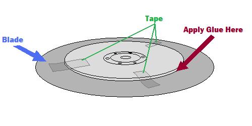
A little fiddling and re-alignment will get things pretty close. After the centering is good, the next step is to glue the blade into place. I used tiny drops of Zap-a-Gap around the inner edge of the ring and held the two together firmly as the glue set.
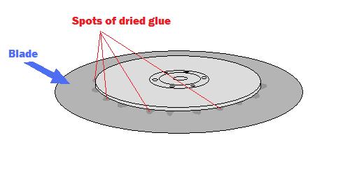
The result is not perfect, but cuts I have done seem to be sufficiently narrow.
The Cutting Setup
The picture below shows the setup for making cuts. The large silver box in the background is the vacuum pump, the green vise in front is holding a digital indicator (for making precisely measured cuts) and the blue airbrush is ready for spraying water onto the cutting surface.
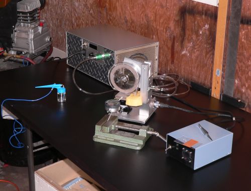
The parts to be cut are mounted on glass slides using Crystalbond adhesive, a thermoplastic mounting polymer.
Using the Chop Saw
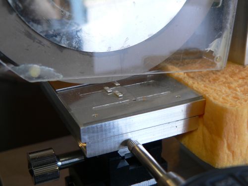
Below are some pictures of cuts made with the saw.
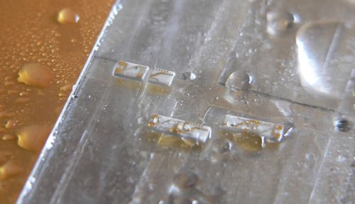
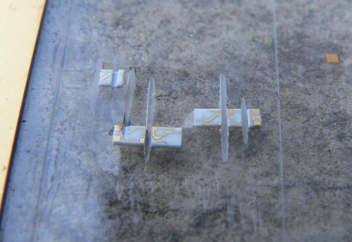
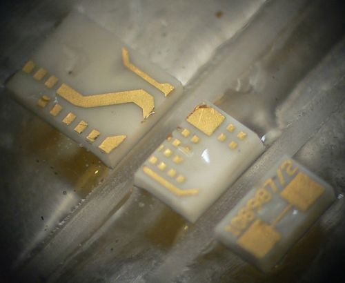
From the photos above it is clear that the saw is working reasonably well. The cuts are straight, the pieces have no obvious large chunks missing, and the gold metallization shows minimal signs of peeling. I have made many cuts using this saw including angled cuts. I have also used the saw to carefully strip off the backside metallization. This will come in handy when I am making diveboard-style waveguide transitions. I have also used the X/Y table to feed the piece along the blade, allowing me to make much longer cuts than in “chop” mode. These came out very nicely as well.
The accuracy of the saw is reasonably good. Using a dial or digital indicator, cuts can easily be made with 0.001 inch accuracy, which is sufficient for circuits working through 50 GHz at least.
One issue that was of concern initially was whether a hard drive motor actually had enough power to do the job. It turns out the motor works fine as long as the cuts are made slowly. Fast cuts are not advisable anyway, as the part is more likely to fly off into oblivion. Some of the substrates I cut had fairly thick metal backing and required slower cuts.
Future Improvements
Every project ends up with room for improvement. With this project a few things come to mind including a precision machined spindle with a better mounting mechanism. This would require a much larger lathe than what I own, and some careful though into balancing. Another improvement would be a self-contained coolant sprayer and vacuum pump for the chuck. Setting up the dicing saw currently requires a vacuum pump, an air compressor, and so on. Another nice feature would be a microscopic camera to observe the cutting in action. And finally a CNC retrofit would be nice. All of these upgrades would be handy, but as it is, the saw is immensely flexible and precise. I’m still on the first blade which is showing no signs of wear.
Conclusion
It has been a lot of fun putting together this series of articles and even more fun putting together and using this saw. So if you are planning on putting together a saw like this, happy cutting! If you are just planning on building something with a hard drive motor, they are really handy for certain applications where high precision, high RPMs, and cheapness are required.
Hi, I do some dicing at work.
A few bits of advice.
The rule of thumb for blade exposure on resinoid blades is a 10/1 ratio based on thickness. So a .010″ blade should only have .1″ of exposure.
You should probably get a dressing board to deal with blade eccentricity.
On thicker parts do multiple passes especially when dealing with quartz, which can twin.
Is it me or the blade is just “soldered” with glue ? If yes, it looks dangerous to me!
Very nice job. I had seen a hard drive used for an optical fiber polishing machine, but worried there would not be enough power for dicing. Thanks for documenting and sharing your development!
– Peter
Too Bitchen!
Nice work, Tony!