
Step 1:
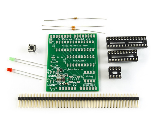
Start by arranging all of the parts of the kit as shown. Make sure you have all of the parts listed.
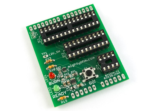
Note: Some parts in the bill of materials come pre-installed on the PCB, as shown.
Parts list:
- (1) Rescue Shield 2 PCB with DC-DC step up converter pre-assembled, as shown
- (1) 1×40 pin breakaway male header
- (1) 28 pin socket
- (1) 20 pin socket
- (1) 8 pin socket
- (1) microswitch pushbutton
- (1) 3mm red LED
- (1) 3mm green LED
- (1) 100 Ohm resistor (brown-black-brown-gold)
- (2) 330 Ohm resistors (orange-orange-brown-gold)
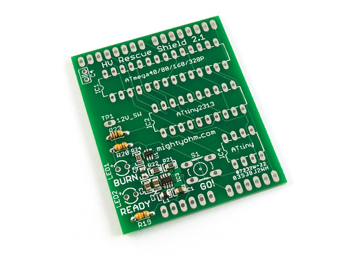
Step 2:
Examine the PCB. The PCB should have some parts already soldered near the lower left corner – this is the surface mount DC-DC converter. This is shown in the photo above.
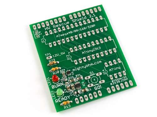
Step 3:
Install resistors R19, R20, and R23. Resistor R19 and R20 are 330 ohms (marked orange-orange-brown-gold). R23 is 100 Ohms (marked brown-black-brown-gold).
Step 4:
Install the LEDs. LED1 is the red BURN LED while LED2 is the green READY LED.
The LEDs have two leads. One is longer, this is the positive lead. Install the LED so the long lead goes into the hole on the left, near the small + symbol.
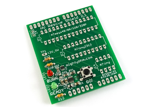
Step 5:
Install the pushbutton, S1.
Step 6:
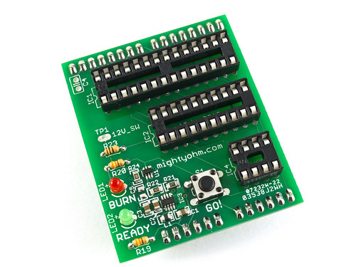
Install the three IC sockets, marked IC1 and IC2, and IC4. (IC3 is the DC-DC converter, which is already soldered!) The notch in one end of each socket should be oriented such that it matches the notch shown in the PCB silkscreen.
Step 7:
Break the 0.1″ header into two sections of 6 pins and two sections of 8 pins. Install the header strips into the board from the bottom side, so the shorter pins stick up through the board, as shown. Make sure the headers sit roughly 90 degrees from the PCB so that they point straight down. I find it helpful to solder one or two pins and check the alignment of each header before soldering the rest of the pins. Another trick is to stick the header pins into your Arduino, and then set the shield on top. This will hold the pins in place while you solder them!
Here is a bottom view of the completed PCB.
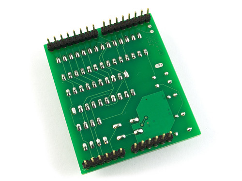
That’s it, you’re done!