
So here’s the background….I’m building a ham radio that operates at 47 GHz. At such a high frequency there are very few components that can be soldered on to circuit boards, let alone components that even come packaged! The easiest way to build a high performance radio at these frequencies is to use MMICs (Monolithic Microwave Integrated Circuits). These are really just fancy, yet fairly simple circuits made from exotic materials, most commonly Gallium Arsenide (GaAs) instead of the usual Silicon used for normal chips. Before MMICs were in widespread use, individual transistors had to be used, requiring delicate and hard to make external matching elements. MMICs are like nice little 50 ohm building blocks. Low Noise Amplifiers (LNAs), mixers, Power Amplifiers (PAs), phase shifters, etc. etc. are all available in this form. Trouble is that you have to connect these pieces up to make a functional radio (or at least the microwave portion of it).
Wire bonding is the usual method for connection and is really just a method of welding a wire (or ribbon) from one chip to the next. It turns out that you actually need space in between the chips, for thermal reasons, RF reasons, and for placing the requisite bypass capacitors. So what goes in between the chips? Well, coax cable is pretty much out, and most common circuit board materials start getting pretty lossy at 10+ GHz, and even the good stuff (PTFE-based usually) starts getting kinda lousy at 40+ GHz. At very high frequencies, materials like ceramics and quartz become worthwhile. In my radio I chose to use pre-made alumina ceramic substrates (tiny circuit boards). These come with a gold layer on the back, and a gold line on top etched to perform as a 50 ohm transmission line (just like coax and just what the MMICs want to see). I bought these with a number of other hams last year in a group buy. They are fairly expensive being that they are 5 and 10 mils thick!
To make the best use of the sections that I bought I decided I needed to cut them to length. Well how do I do that? The thickest pieces are 10 mils thick (a piece of printer paper is 4 mils thick) and they are brittle! Beyond cutting, how do I hold the piece while cutting and when it’s done? The resulting pieces may be just 100 mils long, and 50 mils wide. Obviously a pair of vice-grips simply won’t do.
So my first thought was a Dremel tool and tape. This method could work, but it does not lend itself well to making measured cuts. At 47 GHz, a few hundredths of an inch is a lot! Also, the available diamond blades for dremel tools are fairly wide and I wanted to waste as little of the small substrates as possible. At this point I made a lucky find on eBay.
In the semiconductor industry, one of the last steps of making a chip is called “wafer dicing.” After a wafer full of chips is made, they need to be cut out into individual parts. To do this, wafer dicing machines were developed. These are CNC saws that use a high speed (as high as 60,000 rpm) air bearing spindles with diamond abrasive blades. They can cut lines across large dinner plate sized wafers that are as narrow as only a few tens of microns. Luckily there is enough wafer dicing going on in the world that there is a source of surplus blades on eBay. Not all blades are well suited for all materials, so do some research if you are interested. Disco (a Japanese company) is one of the largest dicing blade manufacturers.
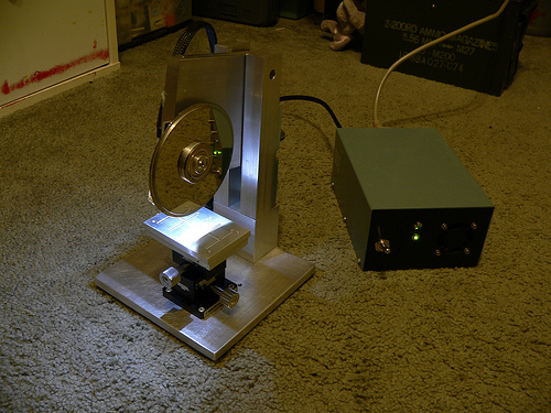
While reading the last paragraph you may have spotted a few words indicating unobtanium. Those words are “high speed air bearing spindle.” Well I chose to use a hard drive motor instead, because they have excellent bearings and are readily availble for free. While they don’t move as fast, I don’t care. I have a few short cuts to make, not millions of chips.
So that is an introduction to what I’m doing. For the most part the saw has been built using surplus parts and remnant pieces of metal from my favorite local metal supply house M&K Metals in lovely Gardena, CA. As of this entry, the saw is nearly complete, all that is left is the splash guards. I’ll be posting the build of this project in several parts, so stay tuned.
And a link to my Flickr photo set for this project: Dicing saw
-Tony
Whats up this is somewhat of off topic but I was wondering if blogs use WYSIWYG editors or if you have to manually code with HTML. I’m starting a blog soon but have no coding expertise so I wanted to get advice from someone with experience. Any help would be greatly appreciated!
I definitely saw the first picture, and the first thought that came into my head was, “Is that a hard drive motor?”
Totally impressed! Not just great engineering but a lot of lateral thinking. I love the repurposing of the hard drive – talk about ‘not reinventing the wheel’!
I have been looking for a way to do this kind of precision for while and now I know how. But I have a question: It looks like you have been doing some very hi res etching too, do you have a solution to that or have you found a very good pcb house?
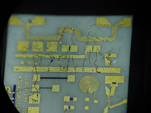
All the etched parts you see are scrap pieces. I haven’t figured out a way to etch yet. There are a number of issues here that are challenging. First is the mask, although from what I understand, photoplotting houses will do very high resolution masks fairly cheaply (~$25 range onto transperency material). These would exceed the capability of anything you could hope to print at home.
So once you have a mask you need to etch. I believe that many of the available substrates are gold on top of a resist material/buffer like NiCr, etc. So you’ll need to come up with the nasty chemicals used for etching these…
Then there is the issue of coming up with the material to begin with. I haven’t yet found a supplier of metallized ceramics, but I’msure they are out there. On the other hand you could find an evaporator and try it yourself 🙂
I would figure at minimum $1000-$5000 for a run of your designs at a fab house for ceramic substrates. That could give you a bunch of parts and if that makes sense for your application could end up being only a few dollars per piece. Another advantage with that is the laser drilled and possibly filled vias, that would be very challenging to do on your own.
Man, i never knew a saw could get so precise. I’ve seen some monsters at the other end of the scale but not something like this…good work! i’m off to read the next 2 parts
Looks pretty good. Just starting to get into lower uwave bands myself. Building a few transverters for 2meters. Scavenging components from LNA’s and LNB’s, and a few MMICs from Mini-Circuits.
How did the hard-drive saw work out? I was curious whether or not the motor would have the torque along with its RPMs to to cut the substrate or would it bog down in the material?
Mark , KB3PGM
The saw works great! I have cut at least 10 substrates now with it and the motor has plenty of torque to cut through even 20 mil thick substrates on metal backing. I need to write part 4 of this with the results….
Tony – There is no such thing as patience on the internet. More information now please!
Updates?
Coming soon!
WOW!! This kid is AMAZING!!! -Steve Long, Tony’s Father :-))
This is properly cool. It’s nice to see that hobbyists are willing to keep up to date with technology to the point where they make things by hand that were only ever intended to be manufactured with an automated process.
Personally I’m even struggling with (large) surface mount packages so I don’t think I’ll get down to Tony’s level of precision without computer assistance!
Wow, this a wonderful project. You are a clearly very talented. I can’t wait to see your follow-ups.
what do you mean by mils? Millionths of an inch?
1 mil = 0.001 inches (one thousandth of an inch)
An incredibly entertaining read! Looking forward to more installments.
Absolutely! Some of the hard drives I tested would spin up, realize they were missing almost all their parts and then spin down. Luckily this drive is dumb enough to just keep spinning. This avoids having to build/buy an electronic speed control. More details on all of that in upcoming installments 🙂
Wow! Seriously cool project. Will you have to keep the hard drive “motherboard” to run the hard disk motor?