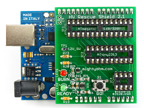
It took a couple weeks longer than I expected, but HV Rescue Shield kits are back in stock now.
Order yours today!

It took a couple weeks longer than I expected, but HV Rescue Shield kits are back in stock now.
Order yours today!
This week I finally received my Bus Pirate v4 from Seeed Studio.
The first thing I did after opening the box was to probe the 3.3V rail with the BP internal power supply enabled.
Here’s what I saw:

That looks familiar! Except this time it’s an oscillation at 5.9kHz and 400mVpp! (almost 4 times what I saw on the SFE Bus Pirate).
I replaced C11 with a 4.7uF tantalum surface mount cap that I scavenged from another board, and the oscillation went away completely:

Ahh, that’s better!
Again, I strongly suspect the low ESR of the ceramic cap is to blame. The 3.3V regulator really needs to see the higher ESR of a tantalum or electrolytic cap for stability.
My advice to all Bus Pirate owners is to check your 3.3V rail with a scope, if possible, and replace C11 with a tantalum or electrolytic cap. Alternatively you may be able to add a small amount of resistance in series with the ceramic cap that comes with the Bus Pirate, but I haven’t verified this.

I picked up this Sparkfun Bus Pirate a couple years ago (thanks to Free Day!) It sat in a box for most of its life until recently I needed a simple way to interface a PC to an I2C device at work. Out came the Bus Pirate.
I’m fortunate to have an Agilent MSO-X 3000 series scope at the office. This scope includes I2C decode capability on both analog and digital channels. I had been having some trouble with corrupt data coming in on the digital channels, so before connecting the Bus Pirate I switched to using analog channels 1 and 2 to decode I2C clock and data instead.
After sending a few test packets with the Bus Pirate, I noticed something weird – the logic high level had a tiny sawtooth waveform riding on it. Not good.
I zoomed in and saw something like this:

That 15kHz sawtooth is almost 150 mVpp!
After removing my device under test, I quickly narrowed the problem down to noise on the Bus Pirate’s 3.3V rail. I initially suspected that this might be some kind of noise coming from the 5V USB supply, so I added an additional 10uF cap in parallel with the 1uF already on the board (C1). The sawtooth increased drastically in amplitude and went down sharply in frequency. That’s when I realized that this wasn’t noise, it was a power supply oscillation.
The Bus Pirate uses a Micrel MIC5025-3.3YM5 regulator (VR3 in this schematic) to create the 3.3V rail from USB’s 5V. In the datasheet, there is a familiar warning: “Ultra-low-ESR capacitors can cause a low amplitude oscillation on the output and/or underdamped transient response.” The Bus Pirate uses a ceramic cap for C1, I’m not sure of the type but it could easily be NPO/C0G and quite low ESR. Adding another 10uF ceramic cap lowered the ESR (and SRF) of the parallel combination, bad news for supply stability.
Realizing that low ESR of ceramic caps was likely part of the problem, I took a different approach. I went around the lab and found the crappiest cap I could find, a 1uF/50V electrolytic, and put that across C1 instead.
After adding the new cap, this is what the 3.3V rail looks like:

No more oscillation. This is with the original C1 still in place (see the photo at the top).
I don’t think Sparkfun has changed the design of their Bus Pirate clone in the years since I purchased mine, so if you’ve got one of these on your bench, throw a scope on the 3.3V DUT supply (after enabling it) and see what you find. You might be surprised.
Unless I am mistaken, a very similar regulator & bypass cap is used on all Dangerous Prototypes v3 and v4 Bus Pirates (including clones), so this is something to watch out for on any Bus Pirate on the wild.

Photo credit: bionerd
Soldering is Easy got a shoutout from Lifehacker’s Thorin Klosowski this week in his post How to Get Started with DIY Electronics Projects, alongside Ladyada’s “E is for Electronics” coloring book.
Lots of great advice here:
One of the key things to learn right off the bat is that expert experience isn’t required for DIY projects. You just need an idea of what you want to make, and from there you can find tutorials guiding you through the process.
Sage words.
UK artist Nikki Pugh posted this video of her Star Jar, a Geiger counter triggered LED decoration for the holidays. This project is based on her holiday light display from last year. This version incorporates fading transitions is completely powered by the mains.
The light changes are triggered by a MightyOhm Geiger counter kit which detects background radiation and cosmic rays.
If you’re interested to learn how this project was made, check out the instructable.