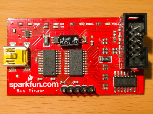
I picked up this Sparkfun Bus Pirate a couple years ago (thanks to Free Day!) It sat in a box for most of its life until recently I needed a simple way to interface a PC to an I2C device at work. Out came the Bus Pirate.
I’m fortunate to have an Agilent MSO-X 3000 series scope at the office. This scope includes I2C decode capability on both analog and digital channels. I had been having some trouble with corrupt data coming in on the digital channels, so before connecting the Bus Pirate I switched to using analog channels 1 and 2 to decode I2C clock and data instead.
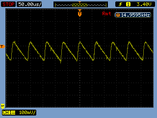
After sending a few test packets with the Bus Pirate, I noticed something weird – the logic high level had a tiny sawtooth waveform riding on it. Not good.
I zoomed in and saw something like this:

That 15kHz sawtooth is almost 150 mVpp!
After removing my device under test, I quickly narrowed the problem down to noise on the Bus Pirate’s 3.3V rail. I initially suspected that this might be some kind of noise coming from the 5V USB supply, so I added an additional 10uF cap in parallel with the 1uF already on the board (C1). The sawtooth increased drastically in amplitude and went down sharply in frequency. That’s when I realized that this wasn’t noise, it was a power supply oscillation.
The Bus Pirate uses a Micrel MIC5025-3.3YM5 regulator (VR3 in this schematic) to create the 3.3V rail from USB’s 5V. In the datasheet, there is a familiar warning: “Ultra-low-ESR capacitors can cause a low amplitude oscillation on the output and/or underdamped transient response.” The Bus Pirate uses a ceramic cap for C1, I’m not sure of the type but it could easily be NPO/C0G and quite low ESR. Adding another 10uF ceramic cap lowered the ESR (and SRF) of the parallel combination, bad news for supply stability.
Realizing that low ESR of ceramic caps was likely part of the problem, I took a different approach. I went around the lab and found the crappiest cap I could find, a 1uF/50V electrolytic, and put that across C1 instead.
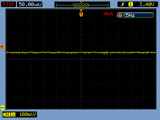
After adding the new cap, this is what the 3.3V rail looks like:

No more oscillation. This is with the original C1 still in place (see the photo at the top).
I don’t think Sparkfun has changed the design of their Bus Pirate clone in the years since I purchased mine, so if you’ve got one of these on your bench, throw a scope on the 3.3V DUT supply (after enabling it) and see what you find. You might be surprised.
Unless I am mistaken, a very similar regulator & bypass cap is used on all Dangerous Prototypes v3 and v4 Bus Pirates (including clones), so this is something to watch out for on any Bus Pirate on the wild.

Thanks for the great investigation and writeup. I pulled all my Bus Pirate production models and tested them. Take a look here:
http://dangerousprototypes.com/2013/03/06/possible-issue-with-voltage-regulation-on-some-bus-pirates/
I see it in the very old SparkFun Bus Pirate I have, but not any of the Seeed Bus Pirate (though this could potentially effect a number of early v3b Pirates if they were fitted with MIC5205s).
the easiest fix for me is just to remove the Mic5205 and change it for a Mic5255 or mic5225 or any other regulator that is stable with low-ERS ceramic caps. The Seed buspirates should not have this problem as they dont actually use micrel parts.
I also have an SFE Bus Pirate, marked 2/10/2010 which also uses the MIC5205 for the Vregs. I also noticed the output noise and added what I had laying around – a 10uF Electrolytic. Soldered that in and yes it got rid of the noise but created a new problem – when you switch on the Vreg I looked at the Vout and saw 5V coming out of the 3.3 Vreg for about 2s, then 3.3V(!). Disconnected the Electrolytic, and it goes direct to 3.3V (with the noise coming back). I’m running this with a Hope RF chip plugged at the end and it’s Abs Max is 3.6V so either 10uF was really throwing off the feedback, or the solution might simply be to replace Cout.
Huh, well waddyaknow… same here, SFE Bus Pirate, marked 2/10/2010
Thanks for the heads up!
Michael
It was pointed out to me (by people much smarter about electronics than I) at:
http://www.eevblog.com/forum/beginners/how-to-crappify-a-cap/
that adding a second cap in parallel to the original will not increase the ESR (which you did mention earlier in your post). You are essentially putting two resistors (the ESR of each cap) in parallel … which reduces the total resistance/ESR.
So why did this work?
See the thread for a very in-depth analysis. I admit that I did not simulate the circuit and didn’t consider how ESR would change vs. frequency.. I suspected that adding the 2nd cap would alter the characteristics of the feedback loop formed by the regulator and bypass cap in such a way that would improve stability, and sure enough it did. It would be interesting to measure the gain and phase margin of the regulator, that would provide much more insight into what is actually happening here. Hmm…
Interesting! I didn’t know LDO regulators were so sensitive to low ESR. If the sawtooth resulted from just steady-state oscillation, I imagine the transient response could be very bad as well. Coincidentally, I am working on a project in which I need to monitor 250KHz serial transmissions between chips, and use the data in my own code.
Fitting an ADP3300/3330 should also fix it. I hate LDOs that can’t take ESR=0, or worse don’t specify what they can take. The ones wth no numerical specification for what minimum ESR will work (guaranteed over temperature) are basically junk.
Yikes! That’s quite an oscillation! Just saw the same thing on my v3.6 direct from Seeed Studio. Nice find. It just goes to show the importance of component selection.