Tag Archives: test equipment

New Flickr Group for your Electronics Workbench

workbench

Ahh, the electronics workbench – shrine to the electron, the diode, the transistor, the soldering pencil and flux pen.

You can learn a lot about someone by looking at their workspace. Note the way that they store components (in pullout drawers or plastic organizers?), hang test leads (on hooks or wire racks, or on a nail?), and keep spools of wire at the ready for repairs and new projects.

A look at someone’s electronics workbench gives you a small glimpse into what is usually a fairly personal space – a space where visions become reality and electronics projects are brought to life.

While there are quite a few electronics workbenches on flickr, I determined after a quick search that there had been no attempt to bring all of these glimpses into a hobbyist or engineer’s soul together into one place.

And thus was born the Electronics Workbench flickr group:

Electronics Workbench

Getting organized in the lab.

Me in my electronics room.  I'm holding the beginnings of a cryogenic receiver project.

Have a photo of your bench? Add it to the group!

No? Then go downstairs into your basement, out into your garage, or up into the attic and take one!

And don’t spend too much time cleaning it up first – noone will believe you that your workbench is that clean when we’re not looking.

Also, a shoutout: This group was inspired in part by the Workbench of the Week (WOTW) page over at The Amp Hour. I don’t think WOTW has been a feature on the show for several months. Maybe we can get Chris and Dave to bring it back??

Happy soldering!

– Jeff

www.flickr.com

items in Electronics Workbench More in Electronics Workbench pool

Tips for finding test equipment service manuals

2009:10:01 02:23:53

When I buy a piece of electronic test equipment, the first thing I do is turn it on and see if it works.  This is the moment of truth: was that awesome eBay find the killer deal I thought it was?  (Hint: If it’s missing case screws and came with no packing material, probably not.)

Sometimes, everything works out and I have a shiny new piece of test gear for bottom dollar.  Often, things don’t work out quite as expected.  Luckily, test equipment is often made to be fixed.

To fix it, I need a service manual.

This means that with my luck, more often than not, the second thing I do is try to track down the service manual for my new semi-functional piece of test equipment.  Even if the it’s not broken, I’ll usually try to get a service manual anyway; often the service manual doubles as a user manual and I need to figure out how to use special features, find specs, etc.

If you find yourself in a similar situation, here are some tips for finding test equipment manuals:

  1. If it’s a fairly new piece of test equipment, chances are the manufacturer will have a manual on their website, usually in pdf format.  For example, Agilent has lots of manuals online, but unfortunately, anything over 20 years old is probably not listed.  Other vendors are better about archiving old manuals.  I have had very good luck getting old Fluke manuals on their website.
  2. Google is your friend.  Are you feeling lucky?  Some manuals are easy to find, like this one for the HP 3312A Function Generator.    The first link that isn’t an ad goes right to it.  Easy!
  3. There are several free service manual repositories on the web.  These can be very hard to find when you need them (spammy links from manual vendors sometimes derail your search).   I have started keeping track of free sources for test equipment manuals on the wiki.  If you are looking for the manual for a fairly common piece of HP/Agilent or Tektronix gear, there’s a pretty good chance you’ll find it for free on one of the sites listed.
  4. As a last resort, consider paying for an electronic copy of the manual.  Beware of vendors who are simply downloading readily available manuals for free and selling them to you.  Use eBay with caution.   The wiki now includes a list of reputable service manual vendors.  The only vendor I have used is Artek Media.  They have very reasonable prices and great support.  At $5-$10 a pop, sometimes it’s easier to just buy the manual than scour the web for hours, so it’s nice to be able to trade laziness for dollars.

Usually by step 3 I have the manual I need, so I rarely have to pay for a copy, but it’s nice to know that most obscure manuals can be had for a few dollars.

I hope these tips keep more old test equipment running – remember they don’t make ’em like they used to!

If any readers have more sources for manuals to add, please leave a comment or add them to the wiki.

Test Equipment Pr0n: The HP 3312A

A few weeks ago, I purchased an HP 3312A 12MHz function generator for the lab.  After living without a decent signal source for years, I figured that it would bepo handy to have a good general purpose function generator around.  A quick visit to eBay and a few clicks later, one was on the way.

Unfortunately, when I first powered it up, the output was clamped to one supply rail and the sync output was giving me a much-too-large, out of spec voltage swing.  D’oh!

The generator was sold as-is (like most test equipment on eBay), so I decided to take a crack at fixing it myself.  Armed with a barely intelligible, poorly scanned-faxed-photocopied copy of the 3312A service manual that I downloaded from Agilent’s website, I loosened two captive screws and slid the top and bottom covers off the unit.

What I found inside really blew me away.  What follows are some snapshots of the unit.

The 3312A is the most elegantly designed and well-preserved piece of electronic test equipment I that have ever owned.  The circuit boards, which look brand new, use entirely two-layer  through-hole construction and are laid out with generous component spacing and helpful silkscreen labels.  There is no inter-board wiring to prevent quick removal of any of the PCBs; all of the wiring harnesses use straightforward connectors.  Connections between the top and bottom PCBs are via clever gold plated removable posts that extend through the center panel of the instrument chassis.  The chassis itself, which is cast aluminum, is light but sturdy.  Every aspect of the instrument design appears to have been carefully thought out and is perfectly executed.

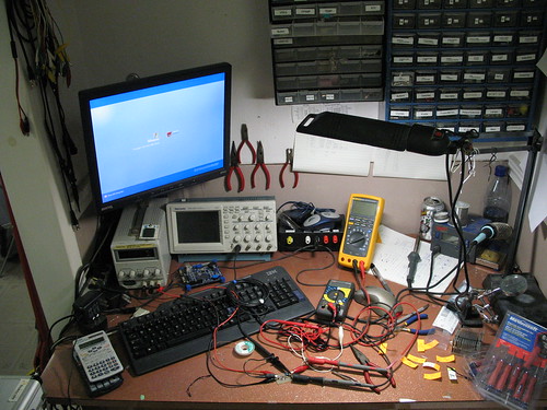
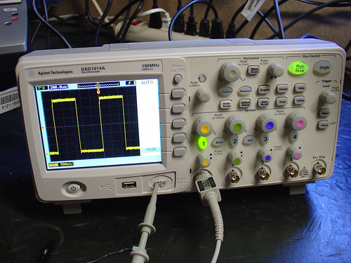
Here’s the 3312A on the bench, ready for some serious troubleshooting action:

HP 3312A Repairs

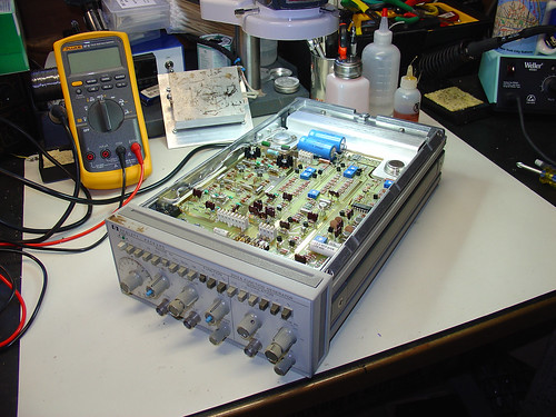
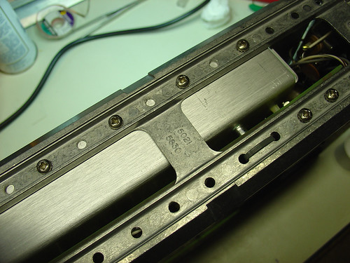
The aforementioned aluminum chassis.  Very nice!

HP 3312A Repairs

When I flipped the generator over, I immediately noticed a problem.  Here are the remains of four 200 ohm, 1W carbon resistors, burnt to a crisp:

HP 3312A Repairs

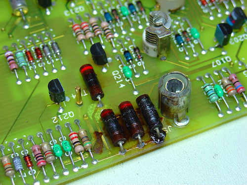
These resistors provide an internal 50 ohm termination for the sync output, and explain why the sync voltage swing was out of spec.  A quick trip to Jameco for some new 200 ohm power resistors and the sync problem was fixed.

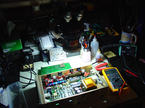
The broken main generator output took some more serious troubleshooting.  One of the emitter follower transistors that drives the push-pull output driver was burning hot to the touch and a good candidate for replacement.  An hour of troubleshooting with the diode test function of my Fluke 87V identified one of the push-pull transistors had failed as well.  This is the device that had failed short and was clamping the output voltage to the -15V supply rail.

The final push-pull drivers are shown here; they are the two devices with the largest heatsinks.  The emitter followers are the two metal can transistors just to the left.

HP 3312A Repairs

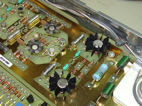
I was able to find suitable replacements for the failed transistors at Jameco.  Neither of the original devices were still available but I was able to find some devices that were “close enough” by examining a few datasheets and cross reference guides.  With the faulty output devices replaced, the generator powered up and was good as new!

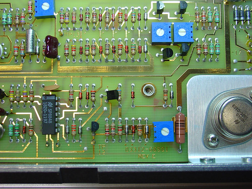
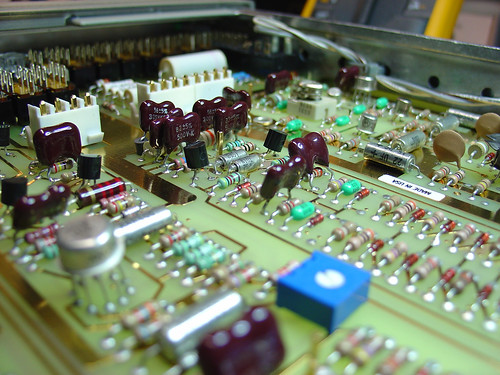
Here’s another couple shots of the main PCB.  Gorgeous gold-plated traces and component layout, and some pretty components too:

HP 3312A Repairs

HP 3312A Repairs

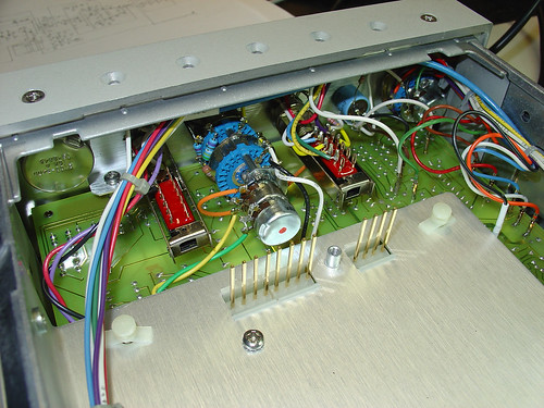
Here’s a shot of the inside of the generator with the top (modulator) PCB removed so you can see the header posts that connect the top and bottom PCBs.  The center aluminum plate that holds the pins in place is also removable.  This allows for rework of components on the bottom (main) PCB without disassembling the entire instrument.  Cool!

HP 3312A Repairs

Want to see more?  Check out the 3312A repairs album on flickr!

Guess the cable length to win stickers!

Part 1:

An HP 3312A function generator is connected to an Agilent DSO1014A oscilloscope via a length of coaxial cable.  The function generator is set to generate a square wave of frequency 1MHz.

Based on the screen capture below, what is the length of the coax cable?

Unterminated Cable
Agilent DSO1014A Screen Capture

The first person to post a comment with:

  • the correct answer within ±10% of the actual measured length
  • a general explanation of how you arrived at this number (show your work!)

gets some free stickers as a reward!

Hints:

    1. The coax is labeled RG58A/U.
    2. The input impedance of the DSO1014A is nominally 1MΩ + 18pF.
    3. In case it’s not obvious, the scope photo shows two curves.  The bottom curve is a zoomed in version of the top one, showing the rising edge only.  This means that the time per division for the bottom curve is different from the top curve.  Thankfully, Agilent shows the time/div at the bottom of each so you don’t have to guess!

      Part 2 (Extra Credit):

      The function generator claims to have an output impedance of 50Ω.  Is this true?  Can you make a rough estimate of what the actual output impedance is, based on the screen capture above?

      Note: Random guessing is not allowed.  Please show that you made some honest attempt to solve the problem, even if it is by unconventional means!

      My new oscilloscope – the Agilent DSO1014A

      New Oscilloscope

      Over the Memorial Day weekend I had a chance to spend a little bit of time with my new Agilent DSO1014A oscilloscope.

      The Agilent 1000 family was just introduced on May 4th, 2009.  Since it’s a brand new model, I had to look around a bit to find one in stock at one of Agilent’s distributors.  Agilent quoted a 6-8 week leadtime and said I probably wouldn’t be able to find one anywhere before late June, but with a little searching I spotted one at Newark Electronics.  Two days later, it was running a self calibration in my lab.  Thanks, Newark!

      The DSO1014A is a digital storage oscillscope.  The primary advantage of a digital oscilloscope over a traditional analog scope is that waveforms can be easily captured and analyzed even after the original signal is long gone.  Brief transients in the input signals can be viewed by carefully triggering a digital storage oscilloscope.  This is almost impossible to do with a simple analog scope.

      Here’s a brief feature list for the DSO1014A along with some of my notes:

      • 100MHz bandwidth (the higher end DSO1024A has 200MHz BW)
      • 4 channels (most low cost scopes only have 2, this was a big selling point)
      • 1GS/s sampling rate per channel (pretty standard), 2GS/s in half channel mode (impressive!)
      • 10kpts/channel record length, 20kpts/s in half channel mode (another big selling point for me)
      • front panel USB connector for recording screenshots to USB stick (yes!!!)

      This scope will be a huge upgrade from the analog scope I have been using (an ancient 20MHz Hitachi V212).  While it won’t be able to view USB 2.0 eye diagrams, it should be more than good enough for general purpose use around the lab.

      To see more photos of the scope, check out the full album on Flickr.

      New Oscilloscope
      New Oscilloscope
      New Oscilloscope
      New Oscilloscope

      New Oscilloscope
      New Oscilloscope
      New Oscilloscope
      New Oscilloscope