
Update 01/02/09: A PCB version of this circuit is in the design stages – some preliminary information is here.
Update 03/11/09: Kits based on this design are now for sale!
Update 12/14/10: The original AVR HV Rescue Shield kit has been replaced by the new and improved HV Rescue Shield 2. Visit the HV Rescue Shield 2 product page for information about the new kit!
As I mentioned earlier this week, I recently “lost” an ATmega168 due to flashing the configuration fuses to disable the RESET pin, without realizing that this makes the device impossible to reflash with SPI. This is particularly frustrating because the device is still 100% functional, just completely deaf to ordinary serial programmers. The only way to recover the device is using what Atmel calls “High Voltage Parallel Programming Mode” which very few programmers support, most importantly, not the USBtinyISP I otherwise love.
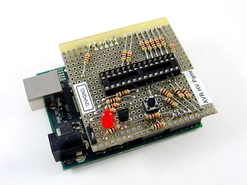
Fortunately, my trusty Arduino came to the rescue – I created an Arduino-based AVR programmer that uses the high voltage programming mode and can fix pesky fuses like RSTDISBL.
The Arduino has just enough IO to implement the entire HV protocol plus a “go” button. So far I have only implemented setting LFUSE and HFUSE in software, but there is no reason why the code couldn’t be extended to support chip erase and programming the entire flash as well.
Overview:
The fuse programming process is simple:
- Upload the HVFuse sketch to the Arduino, available for download here: HVFuse.pde
- Install the shield and apply +12VDC to the terminals on the left
- Wait for the red LED to turn on (if it isn’t already)
- Install the ATmega to be repaired
- Push the button
- As soon as the LED turns back on, the AVR is fixed and ready to be put back into service!
Schematic:
Here is an Eagle schematic of the HV Programming shield (click to enlarge):
Update 12/17/08: An observant reader pointed out that there were three errors in the way GND/AGND, AREF and VCC/AVCC were connected on the target AVR in the original schematic. The errors have been fixed and the updated schematic is below. Apologies for any confusion this caused.

Parts list:
- An Arduino NG, Diecimila, or compatible
- A piece of perfboard cut to size
- Header pins for the Arduino interface (note I had to drill some of the holes to get the headers to fit the nonstandard pin spacing for digital lines 8-13.
- An LED which indicates when it is ok to insert/remove the AVR
- A 2N3903 or similar NPN transistor (2N2222, etc.)
- (20) 1k resistors – these protect the Arduino from short circuits in case something goes wrong
- A pushbutton switch – this is the ‘go’ button
- A 28 pin socket for the target AVR
Kits!
A kit version of this project is available. Visit the HV Rescue Shield 2 product page for more information.
Thank you, it works! Only thing I had to change was adding a pnp transistor (& reversing the output in the sketch) because even with a 500 ohm resistor I still only had ~5,5V at the reset pin (so it was drawing like 10mA?) and it didn’t work.
Datasheet specs 11,5 to 12,5V, by supplying 12V at the barrel jack of the Uno I had like ~11,2V at the reset pin and fortunately it worked.
Glad you got it working! Not sure what’s going on with the voltage drop, I have not seen that before!
really great project.. saving a lot time for fixing atmega..
i wanna know is that code working to atmega32(A) chip?
Thanks! The ATmega32A should support HVPP, so I think this programmer will work. Let me know if you try it!
hayy jeff.. maybe you can help me how to set hfuse and lfuse for atmega32a and atmega128 for external crystal 16mhz..
i already open https://www.engbedded.com/fusecalc/ but a lil bit confused how to change (right) value and get configuration for that.
CKOPT fuse needs to be set for the 16MHz crystal. CKSEL and SUT need to be set for high freq crystal oscillator and startup time based on your application requirements, maybe CKSEL=1111 and SUT=11 is enough to get started. Datasheet has more info.
Hello, Perfect ! I confirm to you that’s running perfectly with ATMega8 and ATMega238 ! Tested today.
Thanks a lot. I had recover 6 Atmega8 with it!
Hey. Tell me, I collected your circuit on the breadboard and tried to fix two Atmega 8. Nothing happened. What fuse-bits are sewn in Atmega – I do not know. What could be the problem?
Hello Arhtur,
This version of the shield is unsupported. To get a professionally produced PCB, all materials to build the kit, and technical support, you can purchase a kit here:
http://mightyohm.com/hvrescue21
I buil dthe shield on a piece of Perfboard and tried to use it with an arduino uno, but it wasn’t working. The RX Led lights up, but the Led on the shield doesn’t. When i connect 12V to the Terminal, insert a brickt avr and press the Button, nothing happens. Do anyone knows, why it isn’t working? Do I have to change the Pinout in the Sketch?
Hello!
This version of the shield is unsupported. To get support, you can purchase a kit here:
https://mightyohm.com/blog/products/hv-rescue-shield-2-x/
I will say that the most common issue is that the later versions of the Arduino sketch only work with the kit and will not work with this early DIY version. This wasn’t done on purpose, it’s due to hardware differences between the kit and the earlier circuit.
Ok, thanks. I will try to build the Kit version.
great at last saved few bucks. recovered 4 atmega 328p.
cool!
hello
I have a Arduino mega 2560
what are the pin configuration should i change
And thanks alot for this
you are a true life saver
The kit version supports the 2560: http://mightyohm.com/hvrescue21
Great tool
built mine on stripe board, and unbricked one Atmega 328p, the ones which are on arduiino
Hi all, anyone knows that the programmer USBASP returns me the following message: ” avrdude : Expected signature for ATmega328P is 95 1E 0F “
Thanx a lot for this marvelous kit.
Finally i was able to reset my 3 mega8 & 2 mega328.
I made the board AVR HV Rescue Shield 2 without the converter & w/o MUN5311.
took 12v directly frm the arduino main input & for transistors used ubiquitous BC547 & BC558 with 1k resistors for biasing.
I made the board using Eagle.
Can i share this board in forums?
Thanx again for ur help to all of us. looking forward for more & more such contribution frm u.
Regards,
Ahmad.
Made an Arduino compatible board using
Arduino Pro Mini with 7805 & not using the
on board regulator as 12v had blown the regulator.
So its important not to connect the RAW pin with 12v.
once again Thankkkkkkk youuuuuu very very very much.
Regards,
Ahmad.
me puede mandar el diagrama [email protected]
Thank you Jeff, I wired ver2 on vero board w/o 5vto12 converter and used components from my junk box, everything is working fine. Thanks- de VU2IIA.
that is great to hear! i assume you were using the sketch from the kit page, and not this one? that might explain why your first attempt didn’t work!