
Last week I posted about the DIY PID-Controlled Soldering Hotplate I designed and built to improve my surface mount soldering capabilities.
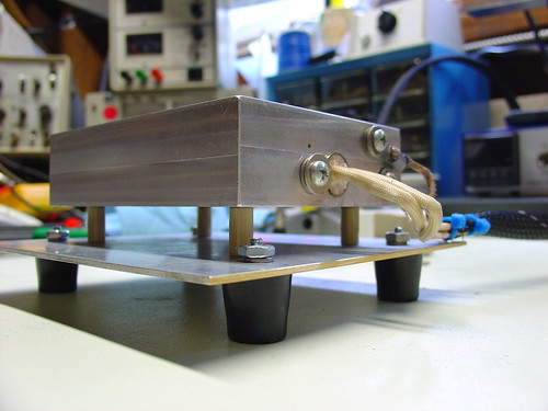
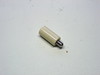
I mentioned one issue I was having with the hotplate on flickr. Specifically, the aluminum baseplate was getting too hot for comfort (literally) when I set the hotplate to solder reflow temperatures (180-220C) for more than a few minutes. At the time I thought it was due to radiant heat from the upper aluminum block transferring to the bottom plate. I later discovered that the ceramic spacers I used to hold up the hotplate were much more thermally conductive than I thought and the screws I used to attach the baseplate to the spacers were burning hot before the rest of the baseplate. It was conducted heat, not radiant, that was the primary cause of the problem!
McMaster-Carr to the rescue!
I was able to resolve the issue by reducing the diameter of the ceramic spacers from 1/2″ to 1/4″ and using all stainless hardware to attach the spacers. Now the baseplate stays relatively cool even with the hotplate at high temperatures for long periods of time.
View the complete set on flickr.
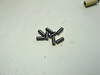
There are 10-32 stainless studs and screws going through the washers that hold everything together. It’s quite sturdy. Also visible is the mechanical relay. I am not sure how long it will last, but i like to hear the click and watch it moving. Its like electricity you can see!
http://www.cellbots.com/wp-content/uploads/2010/08/standoff_detail.jpeg
The only thing I still want to do is mill some heat sink slots in the bottom to reduce the thermal mass and make the fan more effective.
I have built a hotplate based on your design and it works great! Thanks for posting, it gives much more consistent results then the hot air gun. It is 4×6″ and has two 300w cartage heaters. I used thicker 3/8* ceramic standoffs so I fixed the thermal transfer problem by using stainless finish washers, the very thin cupped kind, on the top and bottom of the standoffs. The base dose not even get warm. I bent a base out of steel and put all the electronics in there along with a fan to speed cool-down. Without the fan it stays burning hot for hours!
http://www.cellbots.com/wp-content/uploads/2010/08/IMG_20100804_173033.jpg
Wow, very nice!
One question – with your stainless finish washers installed the way I think they are installed, how do you keep the standoffs from sliding out of position? Maybe I’m missing something. Do you have any pictures of the standoffs showing the assembly?
Nice work, the fan is a nice touch too!
To the person making the hot plate controller. I have a fully funktional temperature controller using a love control which was made just for this type of applications and there has never been a problem of overheating. It could be kept on all day with or without a load on the heater block itself and would never over heat. I can take some pictures of the inside wireing if you would like. Nice job on the heater block by the way. Plastic teflon is a very good heat insulator and can handle very high temps.