I have also been adding more information to the PCB resources page, including where to order cheap solder paste stencils and resources for making test fixtures.
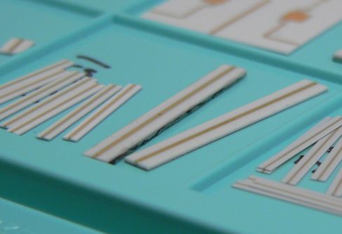
10, 20, and 5 mil thick alumina substrates with 50 ohm transmission lines
In part 1 I gave an overview of what this project is all about. In this part I will describe the basics of the machine and some of the reasons I made the design choices I did. To start with, I wanted to do this on as small a budget as possible. The main project for which this machine serves ends up being a real money pit, so I have to budget accordingly. Hence the use of hard drive parts and scrap metal. Total spent so far is about $60.
When I first thought about how to cut these little pieces of ceramic, it seemed that there were a few elements that would be tricky on a budget. First thing I did was try and figure out how commercial dicing saws work. Certainly Intel and others have figured out a good way to slice ’em and dice ’em a long time ago… And they did.
Tricky thing #1: Holding the substrate while it is being cut.
After a wafer full of chips is finished being made, it is mounted onto a wide stretchy tape, creatively named “dicing tape.” The tape is pulled over a frame and then the wafer placed on top. Next the taped wafer goes into the dicing machine where it is cut by an insanely fast spinning diamond encrusted blade of blingy wafer death.
To keep the wafer from heating up (chips generally don’t like heat) water is sprayed at the cutting surface. This also helps to wash away crud generated by cutting and to prolong blade life. Once the wafer has been diced into individual chips, the tape is exposed to UV light or heat. The adhesive on the tape is made to become less sticky when exposed, and at this point the chips can be easily removed with tweezers, or an automated pick-and-place machine.
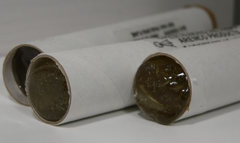
My first thought was to try and get some of this tape and use it in the same manner, but for smaller pieces. Then someone at work told me about something far more cool, with a far better name, something called Crystalbond! Crystalbond is essentially a mounting adhesive designed for exactly what I want to do. You simply heat it up, it becomes liquid, place the part in the puddle, and then do nothing until it cools off and then solidly holds your part. I managed to find 5 lifetime’s supply on eBay for dirt cheap, but several other places sell it. Anyway after the parts are cut you wash it away with acetone and you are left with clean diced parts.
Tubes of Crystalbond mounting adhesive
Okay, so the part can be held, but I didn’t want to have to glue a part to my machine every time I wanted to cut something. So instead of gluing the part to the machine I decided to glue the part to small pieces of glass which are a convenient carrier and can be used with my hotplatethat I built for my wire bonder.
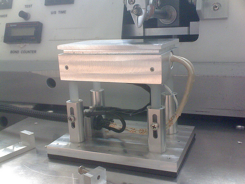
Hotplate for thermosonic wedge bonding
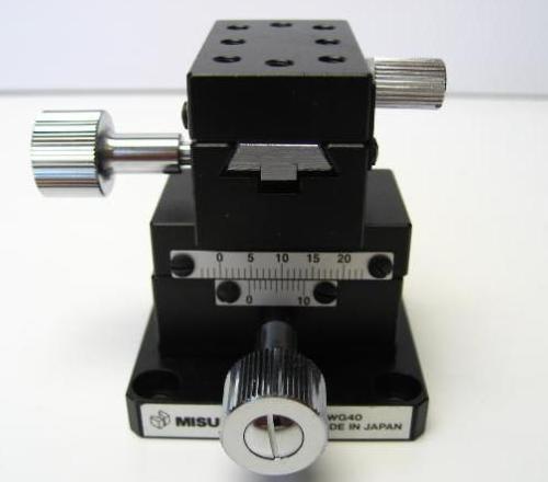
So now I’ve got a piece of easy to handle glass, with one or more substrates to dice which has to be mounted to the machine. I could use tape, a temporary adhesive, or clamps, but why? I just put together a digitally controlled vacuum pump for some composites work, so why not make a vacuum chuck? And even better, I mounted it to a precision X-Y dovetail slide that I purchased on eBay for cheap. Now I can easily position the glass, reposition if necessary, and make measured cuts my moving the X-Y stage and measuring at the same time with a runout gauge. This allows me to make cuts that are accurate to 0.001 inches.
X-Y positioner I bought off eBay
A note here regarding XY stages… I chose specifically a dovetail style positioner because unlike the more common linear bearing style slides, a dovetail slide has static loading. The benefit is that there is a much greater resistance to vibration and since I am grinding, I want as solid a mount as possible.
This is really a compound Tricky Thing, a combination of finding the blade, holding it, and spinning it. First a little background on dicing saws and blades…
Wafer dicing used to be done (and still is, especially in research situations) with a diamond scribe, basically a pencil with a diamond at the end. A small scratch is made along the crystal plane of the wafer and then carefully bent until a long, very straight crack is made through the wafer.
The same can be done with alumina substrates, although since it is not a mono-crystalline structure, the crack won’t be as straight or as predictable. Scribe dicing is a relatively labor intensive task and chip manufacturers HATE labor, but even more than that they REALLY HATE any time that an actual person touches a wafer.
Wafer dicing today is usually done with a very thin diamond abrasive blade that grinds away the metal or semiconductor until a cut is made. It is nearly identical to the way you might cut tiles when doing a counter top in your kitchen but on a much smaller scale. When cutting tile, if the blade wobbles a bit or is not centered perfectly, you are not likely to notice. With the alumina substrates I’m working with, the pieces are 20-40 times thinner. This implies that any vibration, wobble, or eccentricity errors can cause problems.
Commercial wafer dicing machines use high speed motors that are carefully balanced and rather than using ball bearings, employ costly air bearings. These are essentially out of reach for hobbyists and really not necessary. What is necessary though is a way to hold and spin the blade accurately. Dicing blades are thin, and the thickest ones I could find on eBay were 300 um wide. At 4.6 inches in diameter, a a very large inner diameter, they are also hard to accurately mount on a typical spindle like that found on a Dremel tool.
Diagram depicting blade mounting: Part A shows the original platter and spacer configuration, Part B shows the modifications I made, Part C shows the blade mounted.
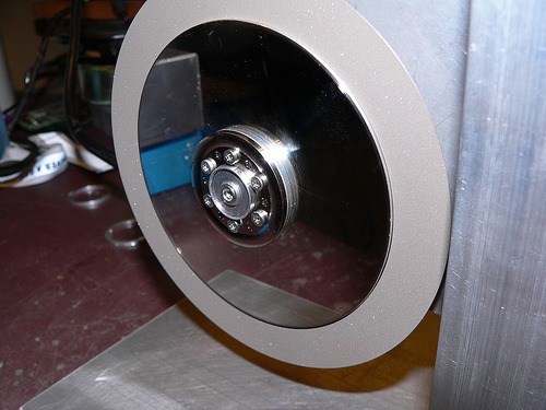
All of these issues led me to use a hard drive motor and platters to spin and hold the blade. Hard drives have very long service lives and need bearings of the highest precision. The mounting of the platters is also done in a precise way, as any imbalance would shorten the bearing lifetime and result in undesirable operation.
To make a long story short, I removed (and reused) the spacer ring between the two platters of a hard drive, and reduced the radius of one platter to 3.5″, the inner diameter of the blade. You can see in the picture that the two platters are stacked and there’s a nice surface for gluing the blade down. Machining the platter down was not easy with my tiny lathe, and it ended up being out of round by perhaps 10 mils. It works to roughly locate the blade, but I will need to tack the blade down, measure, adjust, and finally glue into place. 10 mils out of round is really bad because the thickest substrate I’m working with is 10 mils thick. That means that one part of the blade would never actually do any cutting!
Blade test fitted to the saw.
Tricky Thing #3: Driving the motor
This seemed to be slightly daunting at first. Hard disk motors are typically some kind of brushless motor and require special circuitry to run. I imagined that I would have to build a circuit, or use a motor speed control from a radio controlled plane, etc. It turns out though that the main circuit board in the hard drive I’m using is dumb enough that even though it has had the equivalent of a frontal lobotomy, it just keeps doing it’s job. A couple other hard drives I tore apart did not do this.
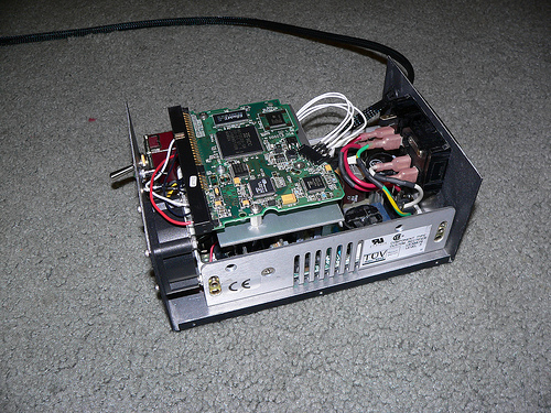
Motor Control Box
The box in the picture above shows the hard drive main circuit board and below that, a 12v/5v switching power supply. It’s pretty basic and at the flip of the switch on the front panel, the DC supply is connected to the motor driver and voila, the motor spins up.
Schematic Diagram for the Motor Control Box
Well, that’s about it for this part. In the next part I will discuss the mechanical structure of the saw, fabrication of a few parts, and in the final installment, the use of this machine.
Based on the date of my first post, last Wednesday marked the one year anniversary of my blog.
While I pour a toast, here are a few highlights of the past year:
PID Controlled Solder Paste Fridge
The first project I documented on the site, my solder paste fridge was the end result of a weekend effort to turn an old beer chest into a PID-controlled Peltier cooler for storing tubes of solder paste. A year later, the cooler has a permanent home under my workbench and is still going strong, keeping its contents at a chilly 36 degrees F. Besides solder paste, I keep my POR-15 rust proofing epoxy paint and a few tubes of superglue in the fridge (they never dry out!).
Space Invaders! Making RGB video with the PIC
I needed an excuse to learn assembly language programming on the PIC, and this project fit the bill perfectly. Instead of slogging through yet another PIC tutorial I decided to “just do it” and the video above shows the result. One of my favorite projects of last year, I have plans to build more of these and make some electronic artwork for the lab.
Bluetooth Handset Hack
One aging bluetooth headset plus one obsolete telephone handset equals one retro-fabulous hack that I still use today. The best part: Look for this one in Make: volume 20!
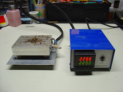
DIY PID-Controlled Soldering Hotplate
I’m a big fan of the hotplate (aka reflow skillet) method of surface mount soldering. Over the course of a few months I designed, machined, and assembled this PID-controlled soldering hotplate to help build the first few prototypes of my AVR HV Rescue Shield kit. Hacking around in the garage is always fun, but creating a new tool is one of the most rewarding things I have can think of.
Here’s a video of the hotplate in action, reflowing the step-up converter on the Rescue Shield:
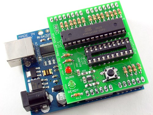
The AVR HV Rescue Shield
What started as a simple hack to save a crippled AVR microcontroller eventually became a kit that I’ve sold to AVR enthusiasts around the world. The AVR HV Rescue Shield includes a cool custom PCB, integrated 5V-12V step-up power supply, and is completely open source. I only made one batch of these, and when they’re gone, they’re gone, so head over to the AVR HV Rescue Shield product page to order one today!
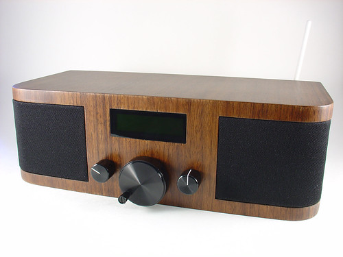
Wifi Radio Project
Certainly the most famous project on the site, my Wifi Radio project has inspired many readers to start playing with cheap wireless routers and embedded Linux. If you haven’t seen it before, the finished project sounds something like this:
I brought the Wifi Radio to the Maker Faire in San Mateo in May. Everyone loved it, including some of the Make: staff, which got me a blue ribbon for the project. Awesome!
Onward!
Well, that’s it for year one… If I missed one of your favorite posts from the past year, leave a comment! If you’re new to the blog, happy reading, you have some catching up to do. 🙂
Here’s to another fantastic year of hacks, projects, kits, tools, and resources at mightyohm.com!
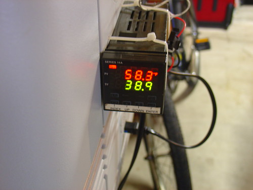
He also posted a bunch of teardown photos (like the one shown below) of the CD101 PID Controller from Sure Electronics. I suspect the CD101 is a cheap knockoff of an RKC PID controller since I can’t find the part number on RKC’s website, even though the front panel clearly says RKC on it. I guess at $40 you can’t ask too many questions, the price is right…