David L. Jones, maker of, among many other things, the awesome uWatch, is producing a really cool Electrical Engineering-themed video blog/podcast called ‘EEVblog‘. I don’t why it took me this long to realize what an informative and hilarious video podcast this is, but a couple recent episodes really sucked me in. I am now a huge fan.
David’s blog actually sprang to life in April of this year, so if you want to watch all of the episodes you have some catching up to do. However, some of the most hilarious episodes are also the most recent. For example, here is David’s very honest review of the Microchip PICkit 3, a development tool for Microchip PIC microcontrollers:
And here is Microchip’s equally hilarious response:
Based on the date of my first post, last Wednesday marked the one year anniversary of my blog.
While I pour a toast, here are a few highlights of the past year:
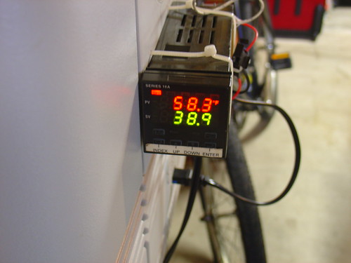
PID Controlled Solder Paste Fridge
The first project I documented on the site, my solder paste fridge was the end result of a weekend effort to turn an old beer chest into a PID-controlled Peltier cooler for storing tubes of solder paste. A year later, the cooler has a permanent home under my workbench and is still going strong, keeping its contents at a chilly 36 degrees F. Besides solder paste, I keep my POR-15 rust proofing epoxy paint and a few tubes of superglue in the fridge (they never dry out!).
Space Invaders! Making RGB video with the PIC
I needed an excuse to learn assembly language programming on the PIC, and this project fit the bill perfectly. Instead of slogging through yet another PIC tutorial I decided to “just do it” and the video above shows the result. One of my favorite projects of last year, I have plans to build more of these and make some electronic artwork for the lab.
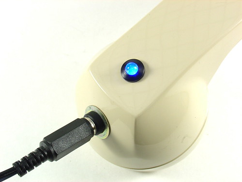
Bluetooth Handset Hack
One aging bluetooth headset plus one obsolete telephone handset equals one retro-fabulous hack that I still use today. The best part: Look for this one in Make: volume 20!
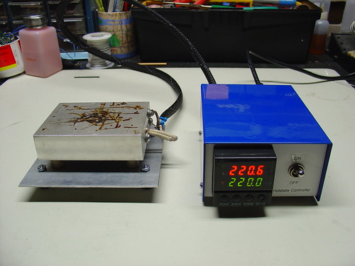
DIY PID-Controlled Soldering Hotplate
I’m a big fan of the hotplate (aka reflow skillet) method of surface mount soldering. Over the course of a few months I designed, machined, and assembled this PID-controlled soldering hotplate to help build the first few prototypes of my AVR HV Rescue Shield kit. Hacking around in the garage is always fun, but creating a new tool is one of the most rewarding things I have can think of.
Here’s a video of the hotplate in action, reflowing the step-up converter on the Rescue Shield:
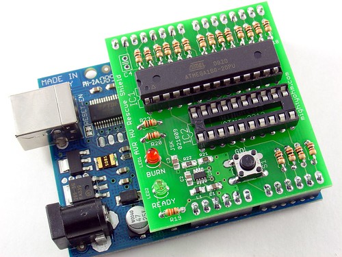
The AVR HV Rescue Shield
What started as a simple hack to save a crippled AVR microcontroller eventually became a kit that I’ve sold to AVR enthusiasts around the world. The AVR HV Rescue Shield includes a cool custom PCB, integrated 5V-12V step-up power supply, and is completely open source. I only made one batch of these, and when they’re gone, they’re gone, so head over to the AVR HV Rescue Shield product page to order one today!
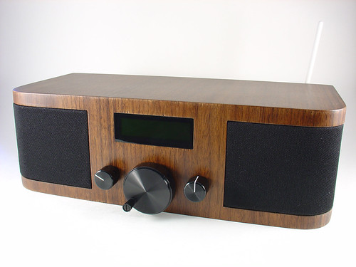
Wifi Radio Project
Certainly the most famous project on the site, my Wifi Radio project has inspired many readers to start playing with cheap wireless routers and embedded Linux. If you haven’t seen it before, the finished project sounds something like this:
I brought the Wifi Radio to the Maker Faire in San Mateo in May. Everyone loved it, including some of the Make: staff, which got me a blue ribbon for the project. Awesome!
Onward!
Well, that’s it for year one… If I missed one of your favorite posts from the past year, leave a comment! If you’re new to the blog, happy reading, you have some catching up to do. 🙂
Here’s to another fantastic year of hacks, projects, kits, tools, and resources at mightyohm.com!
Anyone familiar with the blog knows that I have a special love for internet streaming radio, so it shouldn’t be a surprise that this demo board immediate caught my eye.
The demo board’s features include ethernet, a dedicated MP3 decoder IC, pushbutton user interface, and a cool OLED matrix display. The PIC18F67J60 includes an ethernet PHY on-chip, which makes for a very simple way to add network connectivity to the microcontroller. Sadly, unlike my usual hacking platform, there isn’t any wireless on-board, but given the extremely small size and downloadable source code, I am really tempted to get one of these to play with.
Programming & Customizing PICmicro Microcontrollers, by Myke Predko, is probably the best book out there for someone who is starting out with the PIC series of microcontrollers from Microchip. I used Myke’s book as both a tutorial and reference when I created my PIC RGB Video Display. Since then, I have referred back to this book countless times even when working with other microcontrollers, like Atmel’s AVR family, because it contains so much useful architecture-independent technical information. I have referred to this book for information about topics including LCD interfacing, debouncing switches, RS-232 serial interfaces, and multiplexed LED drivers. As a technical reference it easily surpasses the majority of AVR books that are out there.
The book is starting to show it’s age by not including some of the latest PIC micros in the examples (like the PIC16F628), but the code is easily ported to newer/faster/better microcontrollers, a good learning excercise in itself.
This page summarizes the technical details behind my PIC LCD video project. This is a basic tutorial on how to generate analog RGB video using a PIC16F628 microcontroller.
An LCD screen like the Sharp 4L-U4EB that accepts a noninterlaced NTSC analog RGB video signal (red/green/blue and composite sync all as separate signals). Poor quality datasheet here.
(1) PIC16F628 (the PIC16F628A should be a drop-in replacement. Sorry, I have old PICs lying around.)
A PIC programmer – I am using a K128, but support for it has been discontinued. Microchip’s PICkit2 is probably your best bet, but I haven’t used one (yet).
MPLAB – the free Microchip IDE, or a compatible PIC assembler
(1) 20MHz crystal (HC-18 or whatever fits your breadboard)
(2) 22pF ceramic capacitors
(3) 470 Ohm 1/8W resistors
(5) 10K 1/8W resistors
A 1K potentiometer for brightness control (if needed, my LCD needs one to display anything)
A regulated 5V supply for the PIC, and my LCD needed an 8V supply of its own
Anything else specific to your LCD – hopefully not much.
The LCD I chose for this project needs four main electrical signals to display video. Three of them carry color information – red, green, and blue. These three signals can vary from 0V (black) to 0.7V (full brightness). To achieve this, I placed 470 ohm resistors in series with each, as shown in the schematic. The LCD terminates each color signal with a 75 ohm resistor, so the 470 ohm series resistors serve to convert the 5V output of the PIC to a 0.7V max signal for the LCD (using a resistive divider).
The other signal the LCD needs is CSYNC – an inverse TTL composite sync signal. This signal provides both the horizontal and vertical sync for the LCD. Without these sync signals the image rolls across the display because the LCD doesn’t know where the image starts or ends. Composite sync seems to be a little bit unusual – most RGB video signals have separate horizontal and vertical sync signals on separate wires.
A horizontal line of NTSC video is roughly 64μs long. (μs = microseconds) At the beginning of each line, CSYNC is held low for 4us, then set high again. The RGB lines are held low during sync and stay low for 8μs after sync, then set to the desired levels display the desired image on that line. 2μs before the end of the line, RGB are set low again to signal the end of the visible image. At 64μs, the program loops back to start another line.
You can generate video like this but there would be no vertical hold – the image would be stable in the horizontal direction because we are generating a horizontal sync but not in the vertical direction.
To create a stable image with vertical sync, you have to create a valid “field” of video. We’re creating non-interlaced video, so every field is the same (in contrast with ordinary interlaced video used in television.) A field is composed of 262 horizontal lines. The first line is blank, with CSYNC set low for the entire line. This is the vertical sync. The next 17 lines are called the “blanking interval” and occur above the visible image, during these lines horizontal sync is applied but no RGB signals. The next line is the first visible line and consists of both a horizontal sync and RGB signals as discussed earlier. 243 lines later, we write one blank line, then loop back and repeat the process all over again. Now we have a valid non-interlaced analog RGB video signal.
The blank lines are mostly due to compatibility with old television sets that needed time to reset the electron gun for the next field. The nice thing is that they give us time to do housekeeping before displaying the next field. For example, during the blanking interval I load the image to display into memory so it can be easily read back later.
The critical thing with regards to timing is that the PIC needs to execute the same number of instructions each time it loops, such that the sync signals always occur at the right time. This is why there are a lot of ‘nop’ instructions in my code – to pad the program execution in the right spots and maintain sync. I started by counting instructions to figure out where to put the ‘nop’s, but by the end of writing the program I was using MPLAB’s builtin “Stopwatch” feature instead.
That’s it for now! If you have any questions, make use of these routines in your own projects, or just find this interesting, please leave a comment!