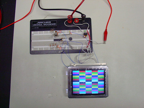
This page summarizes the technical details behind my PIC LCD video project. This is a basic tutorial on how to generate analog RGB video using a PIC16F628 microcontroller.
Previous posts on this project:
- PIC Microcontroller RGB Video – Animations!
- Space Invaders!
- Generating Analog RGB Video with a PIC Microcontroller
Materials needed:
- An LCD screen like the Sharp 4L-U4EB that accepts a noninterlaced NTSC analog RGB video signal (red/green/blue and composite sync all as separate signals). Poor quality datasheet here.
- (1) PIC16F628 (the PIC16F628A should be a drop-in replacement. Sorry, I have old PICs lying around.)
- A PIC programmer – I am using a K128, but support for it has been discontinued. Microchip’s PICkit2 is probably your best bet, but I haven’t used one (yet).
- MPLAB – the free Microchip IDE, or a compatible PIC assembler
- (1) 20MHz crystal (HC-18 or whatever fits your breadboard)
- (2) 22pF ceramic capacitors
- (3) 470 Ohm 1/8W resistors
- (5) 10K 1/8W resistors
- A 1K potentiometer for brightness control (if needed, my LCD needs one to display anything)
- A regulated 5V supply for the PIC, and my LCD needed an 8V supply of its own
- Anything else specific to your LCD – hopefully not much.
Firmware:
- Source code (for use with MPLAB) – lcd_video7.asm
- Hex file – lcd_video7.hex
- Listing file (MPLAB output) – lcd_video7.lst
Schematic:
(click to enlarge)

Theory of Operation:
The LCD I chose for this project needs four main electrical signals to display video. Three of them carry color information – red, green, and blue. These three signals can vary from 0V (black) to 0.7V (full brightness). To achieve this, I placed 470 ohm resistors in series with each, as shown in the schematic. The LCD terminates each color signal with a 75 ohm resistor, so the 470 ohm series resistors serve to convert the 5V output of the PIC to a 0.7V max signal for the LCD (using a resistive divider).
The other signal the LCD needs is CSYNC – an inverse TTL composite sync signal. This signal provides both the horizontal and vertical sync for the LCD. Without these sync signals the image rolls across the display because the LCD doesn’t know where the image starts or ends. Composite sync seems to be a little bit unusual – most RGB video signals have separate horizontal and vertical sync signals on separate wires.
A horizontal line of NTSC video is roughly 64μs long. (μs = microseconds) At the beginning of each line, CSYNC is held low for 4us, then set high again. The RGB lines are held low during sync and stay low for 8μs after sync, then set to the desired levels display the desired image on that line. 2μs before the end of the line, RGB are set low again to signal the end of the visible image. At 64μs, the program loops back to start another line.
You can generate video like this but there would be no vertical hold – the image would be stable in the horizontal direction because we are generating a horizontal sync but not in the vertical direction.
To create a stable image with vertical sync, you have to create a valid “field” of video. We’re creating non-interlaced video, so every field is the same (in contrast with ordinary interlaced video used in television.) A field is composed of 262 horizontal lines. The first line is blank, with CSYNC set low for the entire line. This is the vertical sync. The next 17 lines are called the “blanking interval” and occur above the visible image, during these lines horizontal sync is applied but no RGB signals. The next line is the first visible line and consists of both a horizontal sync and RGB signals as discussed earlier. 243 lines later, we write one blank line, then loop back and repeat the process all over again. Now we have a valid non-interlaced analog RGB video signal.
The blank lines are mostly due to compatibility with old television sets that needed time to reset the electron gun for the next field. The nice thing is that they give us time to do housekeeping before displaying the next field. For example, during the blanking interval I load the image to display into memory so it can be easily read back later.
The critical thing with regards to timing is that the PIC needs to execute the same number of instructions each time it loops, such that the sync signals always occur at the right time. This is why there are a lot of ‘nop’ instructions in my code – to pad the program execution in the right spots and maintain sync. I started by counting instructions to figure out where to put the ‘nop’s, but by the end of writing the program I was using MPLAB’s builtin “Stopwatch” feature instead.
That’s it for now! If you have any questions, make use of these routines in your own projects, or just find this interesting, please leave a comment!
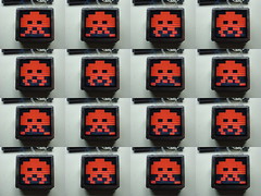 Red!
Red!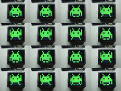 Green!
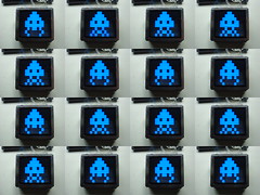 Blue!
Blue!