
In preparation for my Arduino-based AVR HV Programmer boards coming back, I decided to step up my home lab surface mount soldering capabilities.
Step one was to find a cheap stereo zoom microscope on ebay, with 7-32X magnification, perfect for working on surface mount devices. One of my biggest frustrations in the past is that with a cheap magnifying ring light, I can’t actually see what I’m working on – not any more! I’ll post some photos of the microscope when it comes.
Step two was to build a soldering hotplate. I like using a hotplate for surface mount soldering because you can actually watch the board as the solder paste reflows, and manually add/remove/nudge components around with a set of tweezers. This is great for engineering work where you may still be making component changes and other tweaks to the board. Mass production is probably best left to a reflow (aka toaster) oven.
I posted a few photos of the hotplate on flickr, which ended up on Hackaday.
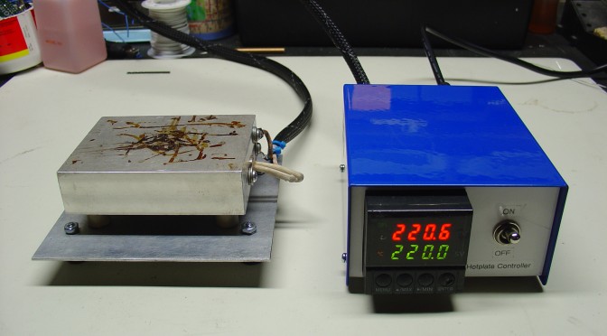
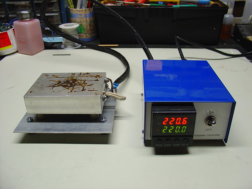
The hotplate:
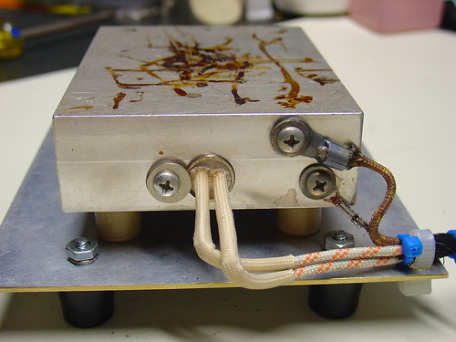
The heater is a 1/2″ 500W, 120VAC cartridge heater I bought from McMaster-Carr for about $25. The hotplate itself is a 3x4x1″ chunk of aluminum that I machined with a carefully sized hole just below the center for the heater to slip into, as shown. A type-K thermocouple (top right) measures the temperature and provides a signal to the controller. Ceramic standoffs insulate the hotplate from the bottom aluminum baseplate. For safety, there is also a ground strap, shown on the bottom right.
This the second PID controlled project I have done, the first was my PID Controlled Solder Paste Fridge.
The controller:
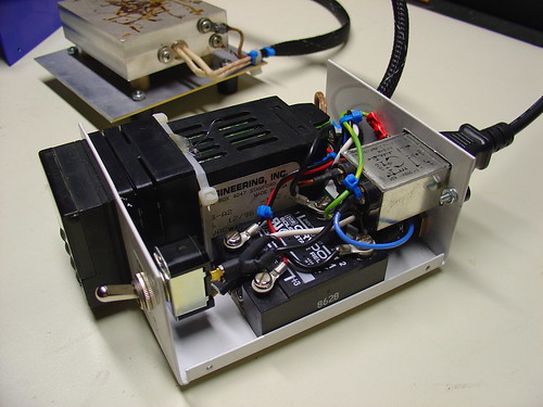
The controller box contains an Omega CN77000 series PID controller and an IR/Crydom 240V 40A (overkill!) D2440 Solid State Relay (SSR), along with a power switch, fuse, and power connector. The PID controller and solid state relay were both found at a now-defunct Silicon Valley surplus store for a few bucks each. A 3′ umbilical cable connects the controller to the hotplate.
60/40 leaded solder reflows at about 185C, and lead-free solder is around 200-230C depending on the alloy. (Wikipedia has a good list of reflow temperatures.) The hotplate can easily reach these within a minute or two from room temperature and could get much hotter if necessary.
It can also be used to cure epoxy and perform any other tasks that require a precisely controlled heater – this could be the world’s most overengineered coffee warmer, if not for the dangers of lead poisioning.
Update: I just posted some more information about the microscope.
hi,
Nice project. That Omega PID controller is a bit expensive. Do you think these PID controllers & SSR’s are safe & usable?
http://www.aliexpress.com/wholesale?catId=0&initiative_id=SB_20160405005312&SearchText=pid+ssr
Or would they have some major disadvantages?
(I’m actually thinking more of making a small furnace for melting metal).
As long as the PID has a SSR output it should work fine – those look like they should work but i don’t have any experience with them.
I am no longer using the Omega – it suddenly died a while ago. I replaced it with a CD101. http://mightyohm.com/wiki/resources:cd101
thanks for the reply. In the meantime I’m exploring the possibility of dropping the PID completely and using a Raspberry Pi running some kind of PID software on it and interfacing to an SSR (possibly needing a 3.3 to 5v level converter). Not sure it will work but it would let me have remote wifi control, program any kind of temp. profile I wanted and log everything too.
Could I wire a few heating catridges,? For example 3 150mmx24 that are 100 watt or would it cause an issue or an over load of the pid?? I’m a welder so not sure on the electric mechanics side
It depends on the PID and the solid state relay, but assuming those components are rated for > 300W it should work.
Could I wire a few heating catridges,? For example 3 150mmx24 that are 100 watt or would it cause an issue
I am thinking of building something similar to this hotplate. I am wondering what material you have used to insulate it from the bench. So far i have considered using calcium silicate to build a stand but your unit looks a bit more elegant!
Nice work though, hope to hear you on The Am Hour again some time.
I used ceramic insulators to insulate the hotplate from the aluminum base, and plastic feet on the aluminum plate to insulate it from the bench.
If I was going to do it again, I would take a thin sheet of stainless steel and attach it to the SIDES of the hotplate with stainless spacers and hardware, then attach the stainless sheet to the base. I found that the ceramic insulators conduct quite a bit of heat, hopefully the thin stainless would conduct less. This is how I have seen others make hotplates, and it seems to work quite well.
To Chris Taylor :
If you want to use Triac, I recommended you to use optocoupler with zero crossing ability, place an optocoupler before triac will isolate the main power line and the phase control circuit, you can use MOC3041.
Great work with your setup! It has inspired me to try something similar with an old laboratory hot plate, fan, k-type thermocouple, and uC (so I can do temperature profiling).
My one question for you is how well does the ssd relay work? Have you had trouble with them burning out? From what I have read they burn out if switched too fast (It isn’t recommended to switch faster than 1Hz) and it seems like the PID controller would cause this. Is this completely off base?
Thanks!
Chris,
The solid state relay only switches once per second. This setting is configurable in the PID controller setup.
I haven’t had an issue with the relay or the ability of the PID to control the temperature, so I’ve been happy with 1 Hz so far.
If you want to get fancy and use proportional control, you could use a triac instead and continuously vary the duty cycle of the heater. This is the recommend way to control cartridge heaters for max life, but I decided that heater life wasn’t going to be an issue and opted for the simpler solution instead.
If you decide to implement a proportional control please share your results!
Jeff
I have never used a PT100 sensor before. I don’t see any reason why it wouldn’t work, provided that your PID controller supports RTD sensors. Thermocouples are cheap and easy to work with, so I used them instead.
I am not using a temperature profile. The hotplate stays at a constant temperature. I just place boards onto the hotplate and let them warm up, The thermal resistance and mass of the board determines the profile. Larger boards can take a long time, and boards without copper on the bottom take longer too. Not the most elegant setup, but it works great.
Dear Jeff,
I’m confusing for the sensor, I decided to make plate with 180mm x 120mm dimension, but my friend says to me for using PT100 not Thermocouple, please give me suggestions. And can you give me the profile for soldering profile, I’m also confused for the profile
Thanks for your aswers, That is good suggestions since difficult find references about DIY reflow skillet or Hot Plate reflow soldering. I would like to using a microcontroller for the PID controller, because I poor for the money, if I buy a Industrial PID Controller. I am college student in mechatronic and interested in SMT, I am very grateful for your advices, I hope you give me another suggestions for my questions in the future.
Pardon me for my ugly english 🙂
Eko,
You might want to check out the Arduino PID Library:
http://www.arduino.cc/playground/Code/PIDLibrary
There may be other PID projects for Arduino or the AVR as well, but that looks like a good starting point!
Hey iam Eko from Indonesia! this is awesome projects, your hot plate size is 4″ x 3″ x 1″, I think I want to make a bigger one, that can be use for euro card 160mm x 100mm, can you give me some suggestion for that! please?
is like, should i use more than 1 heater, maybe 2 pieces, according to the size of the board?
Eko – It should be no problem to scale up the design. I would use two heaters instead of one, maybe 250W or 300W each. I’m not sure what spacing is optimal, but I would probably place one heater 1/4 or 1/3 of the length across the long dimension of the block, and the other heater at 3/4 or 2/3 of the length. A wider separation is probably better since the center of the hotplate will be heated by both elements, and you want to try to flatten the heat distribution across the block. The length of each heater cartridge should match the short dimension of the block. Cartridge heaters are available in all shapes and sizes so it should be no problem to find some suitable for your application!
That is a great idea! I find that hot air rework is much better for removing parts than installing them. That is where the hot plate comes in – for single sided boards, using a hot plate is much easier with less risk of overheating the board.
Nice hotplate! I’m also interested in SMT soldering and got a hot air rework station. A good way of practicing before soldering some valuable components is to desolder TQFP chips from some device, like an usb memory stick and try to solder it back ^^
Lamont – Cool! I have a hot air rework station as well and keep finding more ways to use it.
You could add PID control to a skillet pretty easily, by the way…
nice reflow skillet! I was just going to get a hotplate from a garage sale and use my infrared thermometer to measure the surface temp, but yours looks much more professional. (well, at least industrial)
I just picked up an amazing stereo microscope off of craigslist and successfully used it to figure out just how badly I’d messed up the 0.65mm pitch HTSSOP parts I’d attempted to solder. That plus my hot air rework station make me an unstoppable SMT fixing machine!