Tag Archives: hotplate

Improvements to the DIY PID-Controlled Soldering Hotplate

Improvements to PID Controlled Hotplate

Last week I posted about the DIY PID-Controlled Soldering Hotplate I designed and built to improve my surface mount soldering capabilities.

I mentioned one issue I was having with the hotplate on flickr.  Specifically, the aluminum baseplate was getting too hot for comfort (literally) when I set the hotplate to solder reflow temperatures (180-220C) for more than a few minutes.  At the time I thought it was due to radiant heat from the upper aluminum block transferring to the bottom plate.  I later discovered that the ceramic spacers I used to hold up the hotplate were much more thermally conductive than I thought and the screws I used to attach the baseplate to the spacers were burning hot before the rest of the baseplate.  It was conducted heat, not radiant, that was the primary cause of the problem!

McMaster-Carr to the rescue!

I was able to resolve the issue by reducing the diameter of the ceramic spacers from 1/2″ to 1/4″ and using all stainless hardware to attach the spacers.  Now the baseplate stays relatively cool even with the hotplate at high temperatures for long periods of time.

View the complete set on flickr.

Improvements to PID Controlled Hotplate

New Stereo Zoom Microscope for my Electronics Lab!

Soldering surface mount (SMT) components is tricky, particularly if you can’t see what you are doing due to the small scale of most SMT parts.  Since I started working with SMTs at home I have suffered with a 10x magnifier ring-light.  It works, but it’s tricky to use, mainly because the working distance is so small that getting a soldering iron on a part and keeping that part in focus are almost mutually exclusive.

The right tool for this job is a stereo microscope.  Stereo microscopes use two separate optical paths to provide you with depth perception, very helpful for working with 3-dimensional objects like printed circuit boards.  Even better is a stereo zoom microscope, where the magnification factor can be changed by turning a knob instead of swapping out lenses.

Until now I assumed that a stereo zoom microscope would be way out of my price range, at least several hundred or a thousand dollars for a very basic setup.  However, some searching on eBay showed that good deals can be had, and a used microscope with a boom stand suitable for surface mount work can be found for as little as $200-$300.  New microscopes are available for $400-$500, although there is some debate regarding the quality of low-cost imported microscopes.  Caveat emptor.

For surface mount soldering, 7-30x magnification is reasonable (that’s 10x eyepieces * a 0.7-3x objective), and a 4″ or greater working distance makes using tools under the microscope a lot easier.

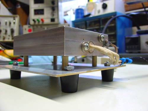
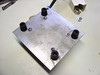
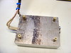
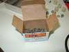
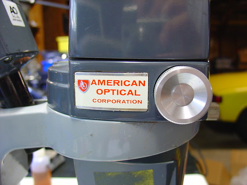
I ended up buying an American Optical (AO) model 569 with an illuminator and boom stand, shown below.  Total cost was just over $200 with shipping.

Stereo Zoom Microscope

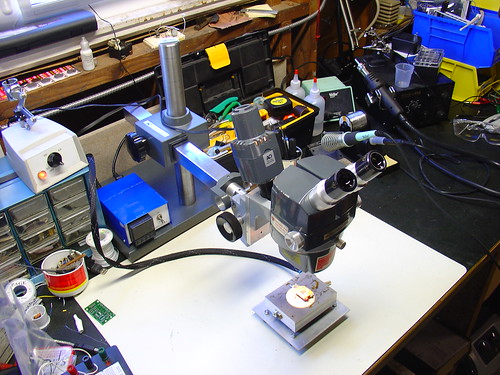
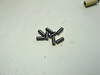
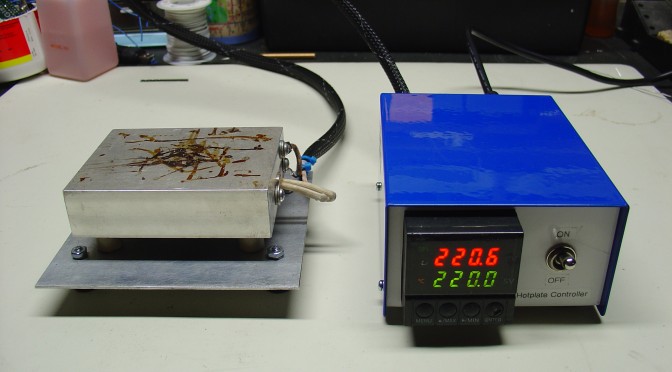
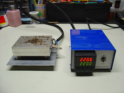
Combined with the PID controlled hotplate I just put together this is a very powerful setup for doing rework of very tiny components – I could probably work with 0402’s, maybe even 0201’s if I was careful.  Using this setup, 0805’s are easy. (and they look huge!)

The scope is very old, it was made in the late 1970s, but it has survived in extremely good condition.  Upon receiving it, I tightened some setscrews and regreased the slides and it’s as good as new, despite being over 30 years old!

American Optical Corporation

There are a few more photos of the microscope setup on flickr.

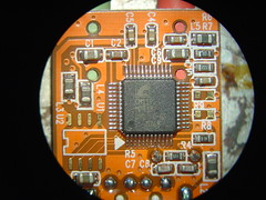
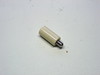
The image quality is excellent.  Here are a couple pictures of my SYBA USB-Audio Adapter taken with the microscope and my Sony DSC-V1 digital camera.  I held the camera up to one eyepiece, set it into macro mode, and snapped the shutter – these images are straight off the camera with no retouching.

Microscope images of the SYBA USB-Audio Adapter Microscope images of the SYBA USB-Audio Adapter

DIY PID Controlled Soldering Hotplate

PID Controlled Hotplate

In preparation for my Arduino-based AVR HV Programmer boards coming back, I decided to step up my home lab surface mount soldering capabilities.

Step one was to find a cheap stereo zoom microscope on ebay, with 7-32X magnification, perfect for working on surface mount devices.  One of my biggest frustrations in the past is that with a cheap magnifying ring light, I can’t actually see what I’m working on – not any more!  I’ll post some photos of the microscope when it comes.

Step two was to build a soldering hotplate.  I like using a hotplate for surface mount soldering because you can actually watch the board as the solder paste reflows, and manually add/remove/nudge components around with a set of tweezers.  This is great for engineering work where you may still be making component changes and other tweaks to the board.  Mass production is probably best left to a reflow (aka toaster) oven.

I posted a few photos of the hotplate on flickr, which ended up on Hackaday.

The hotplate:

PID Controlled Hotplate

The heater is a 1/2″ 500W, 120VAC cartridge heater I bought from McMaster-Carr for about $25.  The hotplate itself is a 3x4x1″ chunk of aluminum that I machined with a carefully sized hole just below the center for the heater to slip into, as shown.  A type-K thermocouple (top right) measures the temperature and provides a signal to the controller.  Ceramic standoffs insulate the hotplate from the bottom aluminum baseplate.  For safety, there is also a ground strap, shown on the bottom right.

This the second PID controlled project I have done, the first was my PID Controlled Solder Paste Fridge.

The controller:

PID Controlled Hotplate

The controller box contains an Omega CN77000 series PID controller and an IR/Crydom 240V 40A (overkill!) D2440 Solid State Relay (SSR), along with a power switch, fuse, and power connector.  The PID controller and solid state relay were both found at a now-defunct Silicon Valley surplus store for a few bucks each.  A 3′ umbilical cable connects the controller to the hotplate.

60/40 leaded solder reflows at about 185C, and lead-free solder is around 200-230C depending on the alloy.  (Wikipedia has a good list of reflow temperatures.)  The hotplate can easily reach these within a minute or two from room temperature and could get much hotter if necessary.

It can also be used to cure epoxy and perform any other tasks that require a precisely controlled heater – this could be the world’s most overengineered coffee warmer, if not for the dangers of lead poisioning.

Update: I just posted some more information about the microscope.