Do you have a question about the Wifi Radio project or want help making your own Bluetooth Handset?
Try asking over at the discussion forums!
If you haven’t seen them before, be sure to check them out!

Do you have a question about the Wifi Radio project or want help making your own Bluetooth Handset?
Try asking over at the discussion forums!
If you haven’t seen them before, be sure to check them out!
The rain and dropping temperatures in San Francisco this weekend reminded me of a project I made in the winter of 2006. This was long before mightyohm.com existed, so I originally documented the project at instructables. I’m not going to repeat everything here, but I wanted to share some pictures and provide a link to the instructable in case anyone else wants to try this at home.
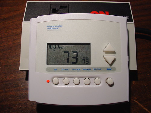
The project involves using a digital programmable thermostat to control an inexpensive space heater. The original motivation for this was that I wanted to lower the temperature of the heater at night, reducing my energy bill, while still being able to wake up to a toasty room in the morning by setting the heater to turn on full blast 30 minutes before I awoke.
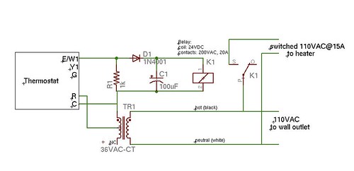
Here’s a schematic of the simple circuit I made to interface the thermostat to the space heater. The resistor/diode/capacitor circuit allows the thermostat, which is designed to control an AC load, to switch power to a 24VDC coil relay. A 36VAC
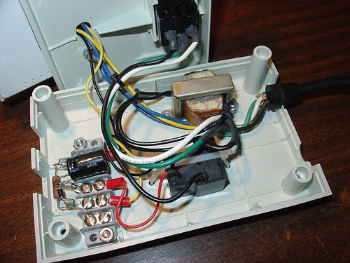
I installed the necessary components inside the case of an old power and telephone line filter, used to protect a fax machine or office copy machine from power surges. The case came with a handy 110V outlet mounted on the front panel which I reused for this project. The digital thermostat mounts to the top cover of the case.
I used a barrier strip as a way to simplify the wiring and mount the few loose components:
I had to adjust the value of C1 to get reasonably clean DC to the relay while not having an annoying turn-off lag when the control line from the thermostat goes low. 100uF works well for the relay I used.
Here’s the finished product installed in my former bedroom:
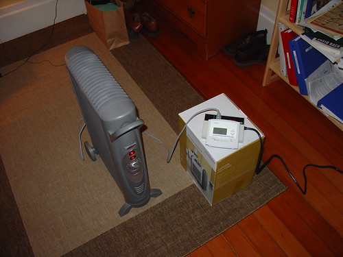
I haven’t used it since I moved into a house with working central heating, but it sure came in handy during the cold winter I spent in a 100 year old farmhouse in Petaluma. This solved the problem of the sub-50 degree mornings I was having nicely!
instructables.com: Space heater controlled by digital thermostat
Comments? Questions? Leave a comment below!
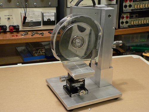
Welcome to Part 3 of the Diamond Chop Saw build. In this installment I’m going to focus on the construction of the mechanical aspects of the saw structure, motor attachment, vacuum chuck, and splash guard. This is a picture-heavy entry…
After thinking for a while about how to build the saw, I decided that it would be best to have the blade move only in the vertical axis, and the workpiece move horizontally in two axes. This led to the overall machine design which consists of a vertical column with pivoting cutting head assembly, and a workpiece holder that has two axes of horizontal motion.
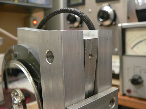
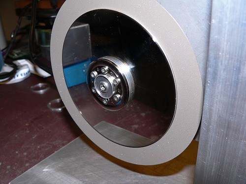
I wanted to ensure the motor and blade had a rigid, heavy mounting structure to reduce effects of vibration and flex on cutting performance. I decided to mount the motor using the original mounting flange from the hard drive enclosure since it was nicely machined to match the motor flange. I used a hacksaw to cut out the shape roughly to size, then straightened up the edges and machined a mounting recess on my milling machine. The L-shaped piece of aluminum is 1/2 inch thick which gives lots of weight and provides sufficient thickness for mounting the bearing while preventing motion orthogonal to the bearing axis.
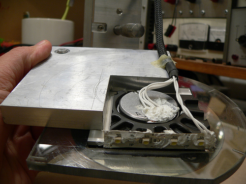
Another view of the cutting head assembly. In the upper left hand corner is the pivot bearing. The bearing is held in place with a set screw that goes through the L-shaped aluminum piece. Along the bottom edge of the black hard drive enclosure portion I attached a strip of white LEDs to help light the work area. RTV Siliconeis used to seal the electrical contacts from water that migt not be caught by the splash shield. At the lower left hand corner of the aluminum plate is a rounded off screw. The cutting depth adjustment micrometer pushes against this rounded off screw. Pushing against the aluminum would be less accurate (aluminum would become unevenly worn).
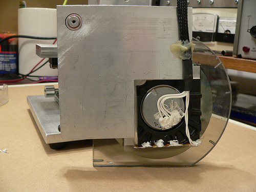
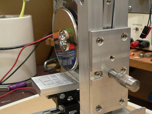
At the top of the column on either side is a hole for the screws that hold the pivot bearing (also from a hard drive) in place. Luckily the one I used has 4-40 threaded holes on either side. A screw on each column holds the bearing in place, and then the rest of the column assembly and adjustment plate are attached resulting in a good alignment of the column to the bearing.
Controlling the depth of the cut is critical, as my cuts will be as small as 5 thousandths of an inch deep! I mounted a micrometer head to a plate on the back of the column which controls the height of the cutting head assembly.
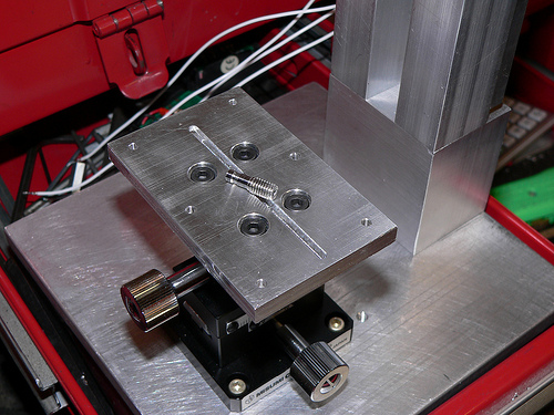
Now for a little detail on the vacuum chuck… The chuck is made from two 1/4 inch plates of aluminum. The top surface has a shallow set of trenches cut to distribute the suction across the bottom surface of the glass plate used for holding parts. The lower plate has a deep trench cut in it to distribute the suction to the three small holes drilled on the top plate. The whole thing is held together with screws and sealed with silicone. I made a set of hose barbs (one is pictured below) so that I can use 1/8 inch vinyl tubing to connect to my vacuum pump. The barbs were made by turning down 10-32 stainless steel screws on my lathe.
The last major component of the saw is the splash guard. This actually took a fair amount of effort to make, as I broke pieces more than once and had to start over. Essentially it is a two-piece design with a thick piece screwed to the cutting head assembly, and a thinner piece which screws onto the first. I used a heat gun to soften the plastic and carefully mold it to the shape of the face plates. I then glued the curved section and the outer face plate together using epoxy and while not very pretty, it holds together well.
In part 1 I gave an overview of what this project is all about. In this part I will describe the basics of the machine and some of the reasons I made the design choices I did. To start with, I wanted to do this on as small a budget as possible. The main project for which this machine serves ends up being a real money pit, so I have to budget accordingly. Hence the use of hard drive parts and scrap metal. Total spent so far is about $60.
When I first thought about how to cut these little pieces of ceramic, it seemed that there were a few elements that would be tricky on a budget. First thing I did was try and figure out how commercial dicing saws work. Certainly Intel and others have figured out a good way to slice ’em and dice ’em a long time ago… And they did.
Tricky thing #1: Holding the substrate while it is being cut.
After a wafer full of chips is finished being made, it is mounted onto a wide stretchy tape, creatively named “dicing tape.” The tape is pulled over a frame and then the wafer placed on top. Next the taped wafer goes into the dicing machine where it is cut by an insanely fast spinning diamond encrusted blade of blingy wafer death.
To keep the wafer from heating up (chips generally don’t like heat) water is sprayed at the cutting surface. This also helps to wash away crud generated by cutting and to prolong blade life. Once the wafer has been diced into individual chips, the tape is exposed to UV light or heat. The adhesive on the tape is made to become less sticky when exposed, and at this point the chips can be easily removed with tweezers, or an automated pick-and-place machine.
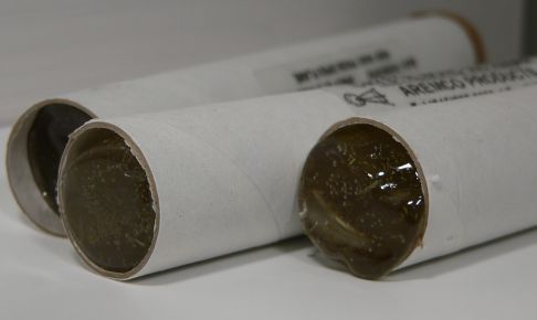
My first thought was to try and get some of this tape and use it in the same manner, but for smaller pieces. Then someone at work told me about something far more cool, with a far better name, something called Crystalbond! Crystalbond is essentially a mounting adhesive designed for exactly what I want to do. You simply heat it up, it becomes liquid, place the part in the puddle, and then do nothing until it cools off and then solidly holds your part. I managed to find 5 lifetime’s supply on eBay for dirt cheap, but several other places sell it. Anyway after the parts are cut you wash it away with acetone and you are left with clean diced parts.
Okay, so the part can be held, but I didn’t want to have to glue a part to my machine every time I wanted to cut something. So instead of gluing the part to the machine I decided to glue the part to small pieces of glass which are a convenient carrier and can be used with my hotplatethat I built for my wire bonder.
So now I’ve got a piece of easy to handle glass, with one or more substrates to dice which has to be mounted to the machine. I could use tape, a temporary adhesive, or clamps, but why? I just put together a digitally controlled vacuum pump for some composites work, so why not make a vacuum chuck? And even better, I mounted it to a precision X-Y dovetail slide that I purchased on eBay for cheap. Now I can easily position the glass, reposition if necessary, and make measured cuts my moving the X-Y stage and measuring at the same time with a runout gauge. This allows me to make cuts that are accurate to 0.001 inches.
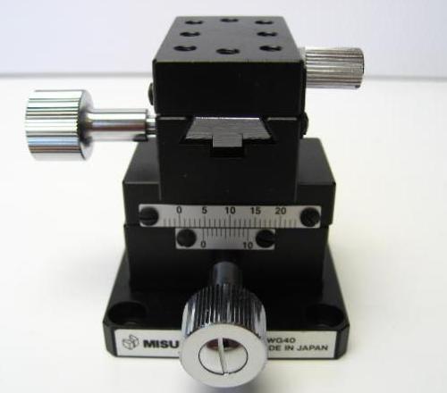
A note here regarding XY stages… I chose specifically a dovetail style positioner because unlike the more common linear bearing style slides, a dovetail slide has static loading. The benefit is that there is a much greater resistance to vibration and since I am grinding, I want as solid a mount as possible.
Tricky Thing #2: The Blade
This is really a compound Tricky Thing, a combination of finding the blade, holding it, and spinning it. First a little background on dicing saws and blades…
Wafer dicing used to be done (and still is, especially in research situations) with a diamond scribe, basically a pencil with a diamond at the end. A small scratch is made along the crystal plane of the wafer and then carefully bent until a long, very straight crack is made through the wafer.
The same can be done with alumina substrates, although since it is not a mono-crystalline structure, the crack won’t be as straight or as predictable. Scribe dicing is a relatively labor intensive task and chip manufacturers HATE labor, but even more than that they REALLY HATE any time that an actual person touches a wafer.
Wafer dicing today is usually done with a very thin diamond abrasive blade that grinds away the metal or semiconductor until a cut is made. It is nearly identical to the way you might cut tiles when doing a counter top in your kitchen but on a much smaller scale. When cutting tile, if the blade wobbles a bit or is not centered perfectly, you are not likely to notice. With the alumina substrates I’m working with, the pieces are 20-40 times thinner. This implies that any vibration, wobble, or eccentricity errors can cause problems.
Commercial wafer dicing machines use high speed motors that are carefully balanced and rather than using ball bearings, employ costly air bearings. These are essentially out of reach for hobbyists and really not necessary. What is necessary though is a way to hold and spin the blade accurately. Dicing blades are thin, and the thickest ones I could find on eBay were 300 um wide. At 4.6 inches in diameter, a a very large inner diameter, they are also hard to accurately mount on a typical spindle like that found on a Dremel tool.
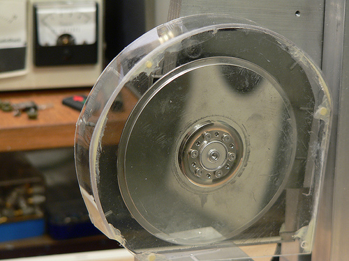
All of these issues led me to use a hard drive motor and platters to spin and hold the blade. Hard drives have very long service lives and need bearings of the highest precision. The mounting of the platters is also done in a precise way, as any imbalance would shorten the bearing lifetime and result in undesirable operation.
To make a long story short, I removed (and reused) the spacer ring between the two platters of a hard drive, and reduced the radius of one platter to 3.5″, the inner diameter of the blade. You can see in the picture that the two platters are stacked and there’s a nice surface for gluing the blade down. Machining the platter down was not easy with my tiny lathe, and it ended up being out of round by perhaps 10 mils. It works to roughly locate the blade, but I will need to tack the blade down, measure, adjust, and finally glue into place. 10 mils out of round is really bad because the thickest substrate I’m working with is 10 mils thick. That means that one part of the blade would never actually do any cutting!
Tricky Thing #3: Driving the motor
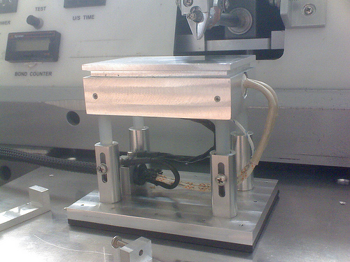
This seemed to be slightly daunting at first. Hard disk motors are typically some kind of brushless motor and require special circuitry to run. I imagined that I would have to build a circuit, or use a motor speed control from a radio controlled plane, etc. It turns out though that the main circuit board in the hard drive I’m using is dumb enough that even though it has had the equivalent of a frontal lobotomy, it just keeps doing it’s job. A couple other hard drives I tore apart did not do this.
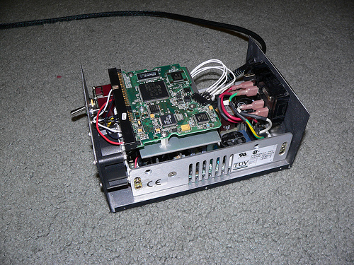
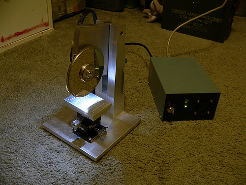
The box in the picture above shows the hard drive main circuit board and below that, a 12v/5v switching power supply. It’s pretty basic and at the flip of the switch on the front panel, the DC supply is connected to the motor driver and voila, the motor spins up.
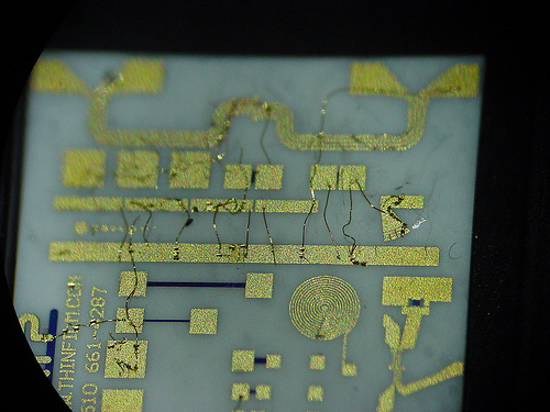
So here’s the background….I’m building a ham radio that operates at 47 GHz. At such a high frequency there are very few components that can be soldered on to circuit boards, let alone components that even come packaged! The easiest way to build a high performance radio at these frequencies is to use MMICs (Monolithic Microwave Integrated Circuits). These are really just fancy, yet fairly simple circuits made from exotic materials, most commonly Gallium Arsenide (GaAs) instead of the usual Silicon used for normal chips. Before MMICs were in widespread use, individual transistors had to be used, requiring delicate and hard to make external matching elements. MMICs are like nice little 50 ohm building blocks. Low Noise Amplifiers (LNAs), mixers, Power Amplifiers (PAs), phase shifters, etc. etc. are all available in this form. Trouble is that you have to connect these pieces up to make a functional radio (or at least the microwave portion of it).
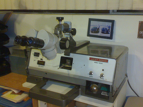
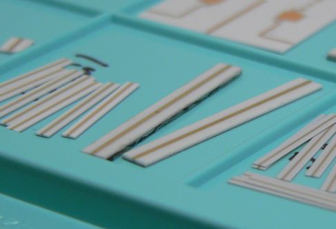
Wire bonding is the usual method for connection and is really just a method of welding a wire (or ribbon) from one chip to the next. It turns out that you actually need space in between the chips, for thermal reasons, RF reasons, and for placing the requisite bypass capacitors. So what goes in between the chips? Well, coax cable is pretty much out, and most common circuit board materials start getting pretty lossy at 10+ GHz, and even the good stuff (PTFE-based usually) starts getting kinda lousy at 40+ GHz. At very high frequencies, materials like ceramics and quartz become worthwhile. In my radio I chose to use pre-made alumina ceramic substrates (tiny circuit boards). These come with a gold layer on the back, and a gold line on top etched to perform as a 50 ohm transmission line (just like coax and just what the MMICs want to see). I bought these with a number of other hams last year in a group buy. They are fairly expensive being that they are 5 and 10 mils thick!
To make the best use of the sections that I bought I decided I needed to cut them to length. Well how do I do that? The thickest pieces are 10 mils thick (a piece of printer paper is 4 mils thick) and they are brittle! Beyond cutting, how do I hold the piece while cutting and when it’s done? The resulting pieces may be just 100 mils long, and 50 mils wide. Obviously a pair of vice-grips simply won’t do.
So my first thought was a Dremel tool and tape. This method could work, but it does not lend itself well to making measured cuts. At 47 GHz, a few hundredths of an inch is a lot! Also, the available diamond blades for dremel tools are fairly wide and I wanted to waste as little of the small substrates as possible. At this point I made a lucky find on eBay.
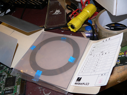
In the semiconductor industry, one of the last steps of making a chip is called “wafer dicing.” After a wafer full of chips is made, they need to be cut out into individual parts. To do this, wafer dicing machines were developed. These are CNC saws that use a high speed (as high as 60,000 rpm) air bearing spindles with diamond abrasive blades. They can cut lines across large dinner plate sized wafers that are as narrow as only a few tens of microns. Luckily there is enough wafer dicing going on in the world that there is a source of surplus blades on eBay. Not all blades are well suited for all materials, so do some research if you are interested. Disco (a Japanese company) is one of the largest dicing blade manufacturers.
While reading the last paragraph you may have spotted a few words indicating unobtanium. Those words are “high speed air bearing spindle.” Well I chose to use a hard drive motor instead, because they have excellent bearings and are readily availble for free. While they don’t move as fast, I don’t care. I have a few short cuts to make, not millions of chips.
So that is an introduction to what I’m doing. For the most part the saw has been built using surplus parts and remnant pieces of metal from my favorite local metal supply house M&K Metals in lovely Gardena, CA. As of this entry, the saw is nearly complete, all that is left is the splash guards. I’ll be posting the build of this project in several parts, so stay tuned.
And a link to my Flickr photo set for this project: Dicing saw
-Tony