Tag Archives: project

DIY Digital Thermostat-controlled Space Heater

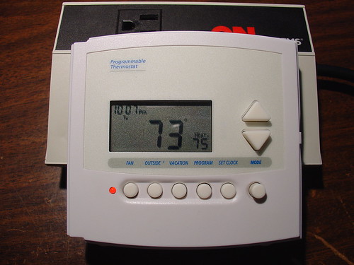
Finished Controller

The rain and dropping temperatures in San Francisco this weekend reminded me of a project I made in the winter of 2006.  This was long before mightyohm.com existed, so I originally documented the project at instructables.  I’m not going to repeat everything here, but I wanted to share some pictures and provide a link to the instructable in case anyone else wants to try this at home.

The project involves using a digital programmable thermostat to control an inexpensive space heater.  The original motivation for this was that I wanted to lower the temperature of the heater at night, reducing my energy bill, while still being able to wake up to a toasty room in the morning by setting the heater to turn on full blast 30 minutes before I awoke.

Here’s a schematic of the simple circuit I made to interface the thermostat to the space heater.  The resistor/diode/capacitor circuit allows the thermostat, which is designed to control an AC load, to switch power to a 24VDC coil relay.  A 36VAC

Space Heater Controller Schematic

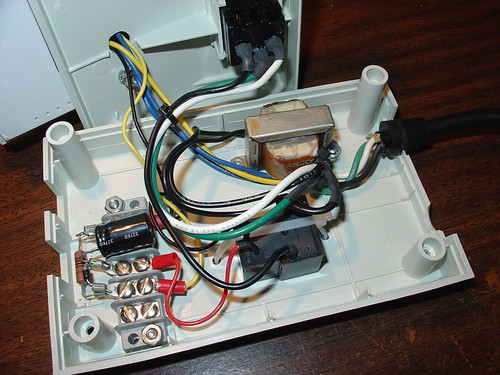
I installed the necessary components inside the case of an old power and telephone line filter, used to protect a fax machine or office copy machine from power surges.  The case came with a handy 110V outlet mounted on the front panel which I reused for this project.  The digital thermostat mounts to the top cover of the case.

I used a barrier strip as a way to simplify the wiring and mount the few loose components:

Space Heater Controller - Inside

I had to adjust the value of C1 to get reasonably clean DC to the relay while not having an annoying turn-off lag when the control line from the thermostat goes low.  100uF works well for the relay I used.

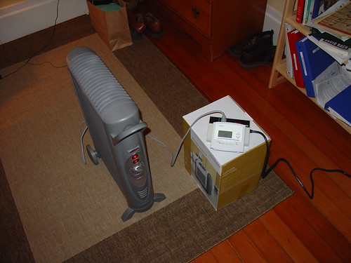
Here’s the finished product installed in my former bedroom:

Controller and Space Heater

I haven’t used it since I moved into a house with working central heating, but it sure came in handy during the cold winter I spent in a 100 year old farmhouse in Petaluma.  This solved the problem of the sub-50 degree mornings I was having nicely!

instructables.com: Space heater controlled by digital thermostat

Comments?  Questions?  Leave a comment below!

Harrison’s Box

A little over a year ago, I became an Uncle.

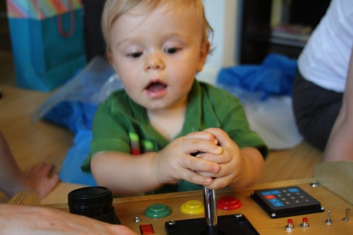
This is my nephew, Harrison.

Harrison

For his first birthday, Harrison’s Mom wanted to give him something really special.  Not just an ordinary toy for a one year old, but something strange and wonderful, tactile, interactive, unique.  Thus was born the idea of an “electric box”, an electronic contraption full of switches, lights, buttons, knobs, levers, and sounds.

An elite task force was assembled to create this special gift, codenamed “Harrison’s Box”.  The team consisted of Grandpa, the Woodworker, Jeff (alias mightyohm) the Engineer, and Kylie, the Project Manager.

Upon defining the project, we immediately jumped into phase one, Procrastination.  Deliverables were met, and as the birthday loomed closer, we eased into phase two, Git ‘er’ Done.

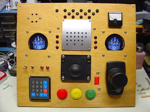
Supplies and materials were ordered, wood chips started flying, and soldering irons blazed.  A short time later, the front panel was realized:

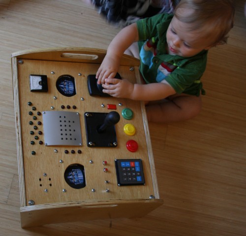
Harrison's Box

Harrison’s box consists of (clockwise from the upper left):

  • A buzzer (sound comes out the four holes)
  • A group of red, yellow, and green LEDs that respond to button pushes below
  • A panel meter (for looks!) from the junkbox
  • A pair of robots with blinking red eyes (aka tradeshow schwag)
  • A pong controller, scrounged at the Prototype This! garage sale on Treasure Island
  • Three large, brightly-colored arcade-style pushbuttons and a large joystick
  • A numeric keypad
  • Some random buttons and switches

Almost all of the electronic components, including the arcade buttons and joystick, were sourced from All Electronics.  A few odds and ends came from my junkbox.

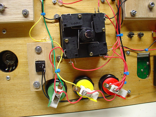
The wiring is point to point – zipties and hot glue keep all of the individual wires in place.  Here’s a shot of the wiring for the pushbuttons and the joystick.

Harrison's Box

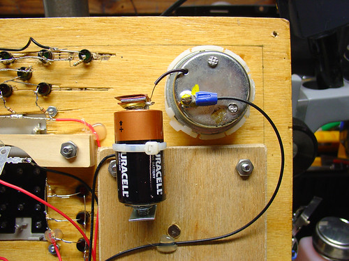
The buzzer consists of the guts of a cheap bicycle buzzer and a single C cell battery to power it.  Some creative wiring allows a pushbutton elsewhere on the panel to control the buzzer.

Harrison's Box

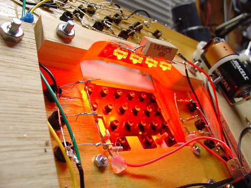
I salvaged a few high brightness red LEDs from a surplus automotive taillight assembly I picked up at Weird Stuff a few years ago.  A 5 Watt power resistor I had in my junkbox limits the current to the LEDs to a bright but not blinding level.

Harrison's Box

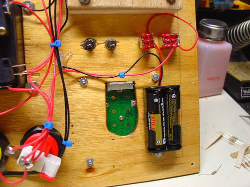
The whole box (with the exception of the buzzer, as noted above) is powered by a pair of AA batteries.

Harrison's Box

Finally, the big day arrived, and it was time to present Harrison (and Mom) with his gift:

Opening the box

Initially the Box was met with some skepticism.  Perhaps Harrison was dwelling on the simple question: Toy or thermonuclear device?  Understandably, there were very cautious button pushes at first.

3544021447_82d005ab4a_o

Moments later, knobs were being turned, switches switched, buttons pushed, and Harrison had learned how to use the joystick.  Look out Steve Wiebe!

Harrison!

The front panel mounts to a small stand that conceals and protects the wiring while also giving Harrison something to hold onto while operating the Box.

Harrison plays with his box

I’m happy to report that Harrison’s Box was a success.

Check out more pictures of the box on flickr.

Building a Wifi Radio – Part 8, Adding a Tuning Control

This is the eighth part of an ongoing series about building a low cost, open source streaming internet radio based on the ASUS WL-520gU Wireless Router.  If you haven’t already, check out the previous parts (see the links at the end of this article) for some background about the project.

In part seven, we added an LCD status display for the radio that shows the stream name as well as the artist and title of the current track.  In this part, we’ll add a tuning knob that lets us change stations without using a computer.

It turns out that this is mostly a software exercise, made simple by taking advantage of the analog to digital converter function of the Atmel ATmega168 AVR that is controlling the LCD display.  The addition of the tuner control turns the display circuit into a very simple user interface.  Turn the knob and the station changes.  The position of the knob determines what station the radio is “tuned” to, and when combined with a calibrated scale it will make it easy to change to any one of the several streaming radio stations stored as presets (favorites?) in the router.

To give you an idea of how this works, here is a demo of the tuner control changing between ten preset stations I have set on the router.  The tuner control is in the upper right hand corner of the breadboard.  As I adjust the control, the music changes and LCD display updates to show the name of each new station.

Is that cool or what?

If you are interested in adding this functionality to the radio, keep reading and I’ll show you how.

Changes to the hardware:

You will need:

  • The completed AVR-based LCD display from part seven
  • A 1k-10k trimmer or potentiometer, linear taper
  • Some hookup wire

Schematic:

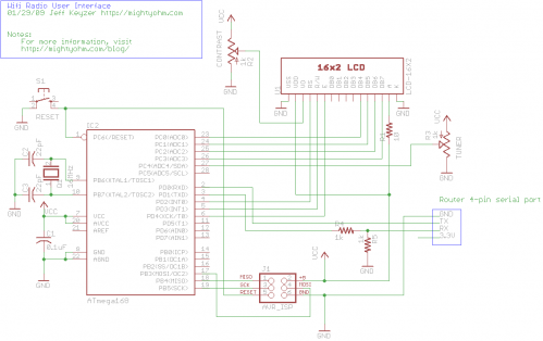
Here is an updated schematic of the AVR circuit showing the potentiometer connected to ADC4 (pin 27).

Wifi Radio User Interface Schematic
click to enlarge

Firmware:

The AVR firmware has been significantly expanded, slightly reworked and cleaned up in some areas.

The most important changes are:

  • The addition of a serial transmit function so the AVR can talk to the router (based on the uart_putchar function)
  • New code supporting the analog to digital converter (ADC) which reads the value of a potentiometer connected to ADC4.
  • A new Timer1 overflow interrupt has been added, which occurs roughly every 0.5 seconds.  The interrupt service routine (ISR) checks the position of the tuner control, and if it has changed, sends the value to the router.  The ISR is towards the top of the file, see the SIGNAL (TIMER1_OVF_vect) section.

The ADC range of the ATmega is 0 – 1024 for an input voltage from 0 to 5V.  The AVR sends serial data in the format “Tuner: Value” back to the router when the tuner position changes by more than ADC_SENS counts (default is 5).  The AVR waits for an “AVR Start!” command from the router before sending any data, this avoids filling up the serial receive buffer on the router before it’s ready to start processing data.  An important consequence of this is that the AVR must be reset before running the control script on the router.

You can download the source code and compiled .hex file here.  Flash it to the AVR using any compatible ISP programmer and you should be good to go.  The source is commented fairly well so if you’re interested in learning how the interface works, take a look.  You will need a copy of the ATmega168 datasheet to understand the register names and other architecture-specific parts of the code.  Feel free to post in the comments with any questions.

Modifying the circuit:

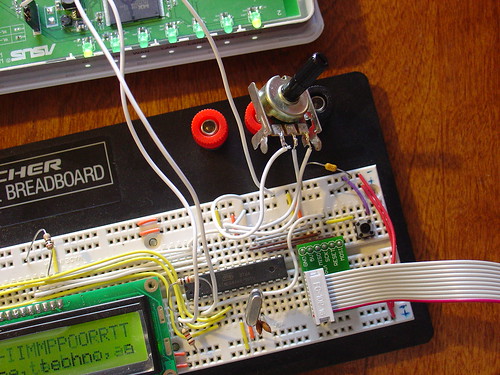
This part is pretty simple – just wire the potentiometer as shown in the schematic.  Most potentiometers have three terminals.  The left terminal goes to ground, the right one to +5V, and the middle terminal to ADC4 on the AVR (pin 27).

Tuner control on breadboard

Tweaks to the OpenWrt configuration:

To make bidirectional communication with the AVR work, we have to change a couple config files on the router and disable some services that would otherwise get in the way.

/etc/config/network

The first change is to modify the /etc/config/network file so that we can always telnet or ssh into the router on a LAN port using the IP 192.168.1.1.  The ability to access the router via ethernet is helpful in case we screw something up and lose the wireless connection or the router loses it’s IP address, etc.

Modify the LAN section of /etc/config/network to look like this (changes in bold):

#### LAN configuration
config interface lan
#option type     bridge
option ifname    "eth0.0"
option proto    static
option ipaddr    192.168.1.1
option netmask    255.255.255.0

Save changes, restart the router, and connect an ethernet crossover cable (straight cable might work on some computers) to the router.  Configure your desktop/laptop computer with a static IP, like 192.168.1.185.  Try to open a telnet connection (or ssh if you have set a password on the router) and see if you can log in.  If not, don’t continue with the next steps until you can get this working.

/etc/inittab

We previously used the router’s serial port to get a login shell.  Now that we’re trying to receive data from the AVR on the same serial port, we need to disable the login shell or it will capture the data before we can get to it.

Edit /etc/inittab to look like this (changes in bold):

::sysinit:/etc/init.d/rcS S boot
::shutdown:/etc/init.d/rcS K stop
#tts/0::askfirst:/bin/ash --login
#ttyS0::askfirst:/bin/ash --login
tty1::askfirst:/bin/ash --login

/etc/sysctl.conf

Sysrq is a fascinating and very low level debugging feature of the Linux kernel.  It can be used to perform troubleshooting operations and reboot the system.  Usually it is invoked with a magic key combination on a desktop computer, but in this case I found that it is easy to accidentally trip over the serial port when using an AVR.  (The “break” RS-232 code triggers Sysrq, this probably has something to do with it.)

Fortunately, it’s easy to disable by editing the /etc/sysctl.conf file and adding these lines:

# Disables the magic SysRq key
kernel.sysrq = 0

Reboot the router to apply the changes.  Now we can get on with the good stuff!

Shell scripting magic:

The real action happens on the router, where a shell script waits for input from the router and changes the station accordingly.

This script is called interface.sh and can be downloaded to the router using wget as shown:

root@OpenWrt:~# cd ~
root@OpenWrt:~# wget http://mightyohm.com/files/wifiradio/interface.sh
...
root@OpenWrt:~# chmod ugo+x interface.sh

The interface script calls an updated version of the display script from part 7, called display2.sh:

root@OpenWrt:~# wget http://mightyohm.com/files/wifiradio/display2.sh
...
root@OpenWrt:~# chmod ugo+x display2.sh

Once both scripts are downloaded, executable and located in /root you can launch interface.sh as follows:

root@OpenWrt:~# ./interface.sh
volume: 60%   repeat: on    random: off
adding: http://relay3.slayradio.org:8000/
adding: http://scfire-dtc-aa01.stream.aol.com:80/stream/1046
adding: http://208.101.28.234:8004

… more stations here …

Tuner Position:  0
New station...
http://relay3.slayradio.org:8000/
[playing] #1/10   0:00/0:00 (100%)
volume: 60%   repeat: on    random: off

The interface script adds ten presets to the router, shows the playlist, and then waits for valid tuner data from the AVR.  Once it receives a “Tuner: value” line (which should occur shortly after the AVR receives a go signal from the script), the script prints the received tuner positon and changes to the requested station.  It will then wait for new tuner data from the AVR and change the station when necessary.

As you can see in the video, this works very well.  Over a fast Wi-Fi connection, the time to change stations is almost instantaneous – very satisfying!

That’s it for part eight.  In part nine, I’ll add some finishing touches to the router configuration and start talking about enclosures.  Stay tuned!

Update: There is a new Wifi Radio Discussion Forum, hop over there to ask questions about the project or see what other people are working on!  (4/12/09)

Update 2: Part nine is now available.

Building a Wifi Radio – Part 7, Building an LCD Display

This is the seventh part of an ongoing series about building a low cost, open source streaming internet radio.  If you haven’t already, check out the previous parts (see the links at the end of this article) for some background about the project.

In part six, we used OpenWrt’s UNIX-style shell commands to interface with mpd, the music player daemon, and redirect song and stream information to our ASUS WL-520gU wireless router’s serial port.  In this part, we’ll use a Sparkfun 16×2 LCD display and a handful of other components to build an LCD status display for the radio.

The Atmel AVR Microcontroller:

After much thought, I decided to use an Atmel ATmega168 AVR microcontroller to drive the display.  I realize that this raises the technical level of this project significantly, but I have been wanting to feature an AVR project on the site and this is a great opportunity.  The truth is that an Arduino would work just as well and it shouldn’t be too difficult to port this program to an Arduino sketch.  (The Arduino is built with the same ATmega168 microcontroller, after all.)  If anyone does this, let me know and I’ll post a link to your version of the display.

If you’re an AVR veteran, you can skip over this part and straight to the bill of materials below.

If you are new to the AVR, don’t be intimidated.  There are a number of tutorials online to help you learn how to use this inexpensive and powerful microcontroller.  I recommend starting with this one or maybe this one, but see my note about AVR MacPack below if you’re using a Mac.  If you’ve never programmed in C before, you’ll have an additional hurdle to get over, although for this project you won’t need any actual knowledge of programming or C to burn the code to the AVR and get things working.

You will need to install some software to work with the AVR, I recommend:

  • AVR MacPack for OS X (the Adafruit tutorial recommends OSX-AVR, use this instead)
  • WinAVR for Windows

I recommend following a tutorial or two and getting a simple blinking LED example working on your AVR before building the LCD display.  That way you can be sure your programmer, development environment, breadboard, etc are working first.

Building the display:

Bill of Materials:

You will need:

also nice, but not required:

  • a Sparkfun ISP breakout board to simplify connecting the programmer to the breadboard
  • a normally-open pushbutton switch to reset the circuit

Schematic:

Here is the schematic of the LCD display (click to enlarge):

Wifi Radio LCD Display Schematic

Firmware:

You can download the source code and compiled .hex file here.

Special thanks to Peter Fleury for his excellent LCD library, which saved me from reinventing the wheel!  He also has another page about interfacing LCD displays to an AVR.

Assembling the circuit:

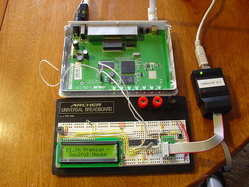
Assembling the circuit on the breadboard is pretty straightforward.  Here’s a photo showing all components of the setup.  The router is shown above with the serial port wired to the breadboard (the RX line is floating as we’re not using it yet).  The USB AVR programmer is on the right, where it is also functioning as a 5V power supply for the circuit. Make sure the 2-pin jumper on the USBTinyISP is installed, this enables the +5V supply.  The LCD is shown displaying the current stream name (DI.fm).

Wifi Radio LCD Display

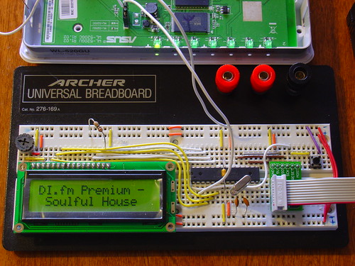
Here is a closeup of the components installed on the breadboard to show how I did things, feel free to experiment with the placement of components.  As long as you follow the schematic the circuit should still work.

Wifi Radio LCD Display

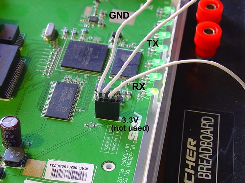
Here is a closeup of the serial port connection to the router, including the 4-pin female 0.1″ header.  I soldered wires to the pins of the female header (not the pins on the board).

Wifi Radio LCD Display

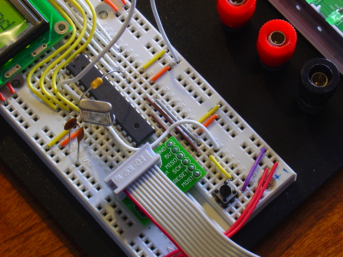
Here is a closeup of the AVR, crystal, and the Sparkfun ISP breakout board showing the pinout:

Wifi Radio LCD Display

Flashing the AVR:

Once the circuit is assembled on the breadboard, we need to flash the AVR microcontroller with the main.hex file included with the firmware above.

If you’re using AVR MacPack and OS X, this should be easy (since that’s what I’m using).  PC guys will need to figure this out for themselves but hopefully the process is similar (please let me know if the Makefile works).

Connect the USBTinyISP to your computer with the USB cable and to the breadboard with the ISP cable.  The green light on the programmer should be on, indicating it is ready, and the backlight of the LCD should be lit, indicating that the breadboard is getting power.

Open a terminal window and create a new directory, I used ~/temp.  Unzip the firmware into a directory somewhere, and execute ‘make flash’, as shown:

macbook:temp jkeyzer$ unzip ./AVR_wifiradio_display.zip
Archive:  ./AVR_wifiradio_display.zip
  inflating: lcd.c
  inflating: lcd.h
  inflating: main.c
  inflating: main.hex
  inflating: Makefile
macbook:temp jkeyzer$ make flash
avr-gcc -Wall -Os -DF_CPU=16000000 -mmcu=atmega168  -c main.c -o main.o

a few warnings later …

avr-gcc -Wall -Os -DF_CPU=16000000 -mmcu=atmega168  -c lcd.c -o lcd.o
avr-gcc -Wall -Os -DF_CPU=16000000 -mmcu=atmega168  -o main.elf main.o lcd.o
rm -f main.hex
avr-objcopy -j .text -j .data -O ihex main.elf main.hex
avrdude -c usbtiny -p atmega168 -U flash:w:main.hex:i
avrdude: AVR device initialized and ready to accept instructions
Reading | ################################################## | 100% 0.01s
avrdude: Device signature = 0x1e9406
avrdude: NOTE: FLASH memory has been specified, an erase cycle will be performed
         To disable this feature, specify the -D option.
avrdude: erasing chip
avrdude: reading input file "main.hex"
avrdude: writing flash (1326 bytes):
Writing | ################################################## | 100% 3.32s
avrdude: 1326 bytes of flash written
avrdude: verifying flash memory against main.hex:
avrdude: load data flash data from input file main.hex:
avrdude: input file main.hex contains 1326 bytes
avrdude: reading on-chip flash data:
Reading | ################################################## | 100% 0.68s
avrdude: verifying ...
avrdude: 1326 bytes of flash verified
avrdude: safemode: Fuses OK
avrdude done.  Thank you.

If everything went well, the LCD display firmware is now loaded into the ATmega168 and the circuit is ready to go.  If not, double check your connections and take a look at the help! page for the USBTinyISP.

Testing the display:

Telnet or ssh into the router.  Start mpd and connect to a stream using mpc (we covered this in part five).

Once the stream starts playing, execute the display.sh script we created in part six.  Within a few seconds, if everything is working, you should see the stream name on the display, followed by the artist and name of the current song.  Congratulations!

Here is a video of the LCD display in action, including the horizontal scrolling feature to show information that is too wide to fit within the visible area of the display:

That’s it for part seven!  In part eight, we’ll start working on the input side of the user interface.

Like what you’re seeing?  Have suggestions about what could be improved?  Leave a comment or contact me directly.

Update: Part eight, in which I add a tuning control to the radio, is now available.

Update 2: There is a new Wifi Radio Discussion Forum, hop over there to ask questions about the project or see what other people are working on!  (4/12/09)

Building a Wifi Radio – Part 6, A Conversation with Mpd

This is the sixth part of an ongoing series about building a low cost, open source streaming internet radio.  If you haven’t already, check out the previous parts (see the links at the end of this article) for some background about the project.

Let’s review…

It’s been a few weeks since I posted part five, so let’s quickly review where we are with this project:

At this point we have a hacked ASUS WL-520gU wireless router running OpenWrt (Linux).   A cheap USB-audio adapter is connected to the router’s single USB port, and in part four we installed kernel drivers for Linux USB and audio support.  In part three we added a connection to the router’s internal serial port via a 4-pin header.  Wireless networking worked pretty much out of the box, and in part five we used opkg, OpenWrt’s package manager, to install mpd, the Linux music player daemon, and mpc, a command-line-based mpd client.

This gives us a compact networked device that can wirelessly connect to streaming radio stations and play 16-bit 44kHz stereo audio on a pair of headphones or amplified external speakers.  Pretty impressive, given that this device started as an inexpensive wireless router!

What’s missing?

Something big is missing from the radio.  The original concept for this radio was that it would be a standalone device.  Shell access is cool, and iPhone control is even better, but ideally we’d like to be able to see what song and station are currently playing as well as change stations without the use of another computer or mobile client.

What we need is a user interface!

Based on our requirements, the user interface needs to do two things:

  1. Display information about what’s playing from mpd
  2. Gather input from the user and tell mpd when to change stations.

A volume control will be part of our finished user interface as well, but it will be simple enough to do this in hardware when we put the radio into an enclosure.  In this part, we’ll start work on the first requirement – the display.

Note: The following steps assume you are accessing the OpenWrt shell through a telnet or ssh connection, not using the FTDI USB-serial cable.  The reasons for this will become obvious later, when we start using the router’s serial port for other purposes!

First of all, how do we get information about what’s currently playing on our radio?

Chatting with mpd:

The command-line program mpc that we installed in part five will return information about the current song if we execute it without any options:

root@OpenWrt:~# mpc
SLAY Radio: Jogeir Liljedahl - Terra Cresta
[playing] #1/5  22:36/0:00 (100%)
volume: 60%   repeat: on    random: off

Mpc obtains playlist, volume, and settings information by sending queries to the mpd server running on the router.  The mpd site includes an overview of the communications protocol and command set.  By default, mpd listens for commands on port 6600.  You can access this port remotely by using one of many client programs, or locally by opening a telnet connection to port 6600 locally (the commands are in bold for clarity):

root@OpenWrt:~# telnet localhost:6600
OK MPD 0.13.0
status
volume: 60
repeat: 1
random: 0
playlist: 14
playlistlength: 5x
fade: 0
state: play
song: 4
songid: 4
time: 2348:0
bitrate: 192
audio: 44100:16:2
OK
currentsong
file: http://relay3.slayradio.org:8000/
Name: SLAY Radio
Title: Jogeir Liljedahl - Terra Cresta
Pos: 0
Id: 0
OK

The connection will timeout in about a minute if left idle.

As you can see, there is a lot of information available, including some of the same information mpc gave us earlier.  The advantage of directly accessing mpd is that we get the stream name (the Name: line) and the artist/title (the Title: line) broken down separately instead of on one continuous line, with handy labels that will make it easy for us to parse the data later.

We can also access mpd by using the nc command, short for “network cat”.  Using nc allows us to easily pipe data from other commands to mpd and examine the results.

root@OpenWrt:~# echo "currentsong" | nc localhost 6600
file: http://relay3.slayradio.org:8000/
Name: SLAY Radio
Title: Jogeir Liljedahl - Terra Cresta
Pos: 0
Id: 0
OK

(As an aside, OpenWrt uses a program called busybox to emulate a UNIX-style shell environment – several common shell commands are included.  There is considerable documentation here, but not all commands listed are actually included in the default OpenWrt busybox installation.)

If we just want the name and title of the current song, we can use the UNIX command grep to strip out just those two lines:

root@OpenWrt:~# echo "currentsong" | nc localhost 6600 | grep -e "^Title: " -e "^Name: "

Name: SLAY Radio
Title: Jogeir Liljedahl - Terra Cresta

Talking to external devices:

Now that we have a way to get song information from mpd, we need a way to direct this information to an external display.  The router comes with a handy mechanism for doing this – the builtin serial port.  Linux makes it easy to direct the output of grep to the router’s serial port, just add a redirect to /dev/tts/0 at the end of the command (all on one line, wrapped here to fit the page):

root@OpenWrt:~# echo "currentsong" | nc localhost 6600 | grep -e "^Title: "
-e "^Name: " > /dev/tts/0
root@OpenWrt:~#

However, it turns out that the serial port’s default speed of 115200 baud is too fast for some external displays.  If we want to be able to talk to an AVR microcontroller, for example, we need to change the speed of the serial port from it’s default value of 115200 to 9600 baud.  This can be done easily with the stty command.

Note: If you downloaded and installed OpenWrt prior to December 3rd by using the files on this site, stty is most likely missing from your installation.  Unfortunately, the only way I know of to easily fix this is to completely reinstall OpenWrt, since stty is part of busybox and included in the base firmware image.  You can check if you have it by executing ‘stty’ from the command line of the router – if you get an error, you will need to reinstall.

You can change the baud rate of the serial port by executing:

root@OpenWrt:~# stty 9600 < /dev/tts/0

Connect your FTDI USB-serial cable to the router’s serial port and open a terminal program set to 9600 baud, 8N1. Execute the last mpd query again, you should see the name and title appear in your terminal window:

root@OpenWrt:~# echo "currentsong" | nc localhost 6600 | grep -e "^Title: "
-e "^Name: " > /dev/tts/0

In the terminal window:

Name: SLAY Radio
Title: Jogeir Liljedahl - Terra Cresta

Now we have a way to get information about the current song and direct it to the serial port.

We can do this is an automated way by using a shell script:

#! /bin/sh -
# display.sh - Wifi Radio LCD display routines
# 12/12/08    Jeff Keyzer    http://mightyohm.com
# This shell script queries mpd for current song information and sends
# relevant bits of it to the serial port, where an AVR-based LCD display
# is waiting.
#
# For more information, visit
# https://mightyohm.com/blog/
#
trap 'exit 1' SIGINT    # exit on ctrl-c, useful for debugging
stty 9600 < /dev/tts/0  # set serial port to 9600 baud
                        # so we can talk to the AVR
while true        # loop forever
do
 echo "currentsong" | nc localhost 6600 | grep -e "^Title: " -e "^Name: " > /dev/tts/0
 sleep 1
done

You can either copy and paste this script to a file on the router, or download it with wget:

root@OpenWrt:~# cd ~
root@OpenWrt:~# wget http://mightyohm.com/files/wifiradio/display.sh
Connecting to mightyohm.com (72.32.209.132:80)
display.sh           100% |*******************************|   668  --:--:-- ETA

Be sure to make the script executable by using chmod:

root@OpenWrt:~# chmod ugo+x display.sh

If you run the script you should see the name and title information update in the serial terminal once a second.

root@OpenWrt:~# ./display.sh

The script will loop forever – hit control-c in the router’s shell to exit.

That’s it for part six!  In part seven, we’ll add an AVR-based serial LCD display to the router – stay tuned!

Update: Part seven is now available.

Update 2: There is a new Wifi Radio Discussion Forum, hop over there to ask questions about the project or see what other people are working on!  (4/12/09)