
This is the eighth part of an ongoing series about building a low cost, open source streaming internet radio based on the ASUS WL-520gU Wireless Router. If you haven’t already, check out the previous parts (see the links at the end of this article) for some background about the project.
In part seven, we added an LCD status display for the radio that shows the stream name as well as the artist and title of the current track. In this part, we’ll add a tuning knob that lets us change stations without using a computer.
It turns out that this is mostly a software exercise, made simple by taking advantage of the analog to digital converter function of the Atmel ATmega168 AVR that is controlling the LCD display. The addition of the tuner control turns the display circuit into a very simple user interface. Turn the knob and the station changes. The position of the knob determines what station the radio is “tuned” to, and when combined with a calibrated scale it will make it easy to change to any one of the several streaming radio stations stored as presets (favorites?) in the router.
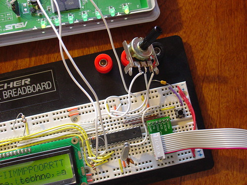
To give you an idea of how this works, here is a demo of the tuner control changing between ten preset stations I have set on the router. The tuner control is in the upper right hand corner of the breadboard. As I adjust the control, the music changes and LCD display updates to show the name of each new station.
Is that cool or what?
If you are interested in adding this functionality to the radio, keep reading and I’ll show you how.
Changes to the hardware:
You will need:
- The completed AVR-based LCD display from part seven
- A 1k-10k trimmer or potentiometer, linear taper
- Some hookup wire
Schematic:
Here is an updated schematic of the AVR circuit showing the potentiometer connected to ADC4 (pin 27).

Firmware:
The AVR firmware has been significantly expanded, slightly reworked and cleaned up in some areas.
The most important changes are:
- The addition of a serial transmit function so the AVR can talk to the router (based on the uart_putchar function)
- New code supporting the analog to digital converter (ADC) which reads the value of a potentiometer connected to ADC4.
- A new Timer1 overflow interrupt has been added, which occurs roughly every 0.5 seconds. The interrupt service routine (ISR) checks the position of the tuner control, and if it has changed, sends the value to the router. The ISR is towards the top of the file, see the SIGNAL (TIMER1_OVF_vect) section.
The ADC range of the ATmega is 0 – 1024 for an input voltage from 0 to 5V. The AVR sends serial data in the format “Tuner: Value” back to the router when the tuner position changes by more than ADC_SENS counts (default is 5). The AVR waits for an “AVR Start!” command from the router before sending any data, this avoids filling up the serial receive buffer on the router before it’s ready to start processing data. An important consequence of this is that the AVR must be reset before running the control script on the router.
You can download the source code and compiled .hex file here. Flash it to the AVR using any compatible ISP programmer and you should be good to go. The source is commented fairly well so if you’re interested in learning how the interface works, take a look. You will need a copy of the ATmega168 datasheet to understand the register names and other architecture-specific parts of the code. Feel free to post in the comments with any questions.
Modifying the circuit:
This part is pretty simple – just wire the potentiometer as shown in the schematic. Most potentiometers have three terminals. The left terminal goes to ground, the right one to +5V, and the middle terminal to ADC4 on the AVR (pin 27).
Tweaks to the OpenWrt configuration:
To make bidirectional communication with the AVR work, we have to change a couple config files on the router and disable some services that would otherwise get in the way.
/etc/config/network
The first change is to modify the /etc/config/network file so that we can always telnet or ssh into the router on a LAN port using the IP 192.168.1.1. The ability to access the router via ethernet is helpful in case we screw something up and lose the wireless connection or the router loses it’s IP address, etc.
Modify the LAN section of /etc/config/network to look like this (changes in bold):
#### LAN configuration
config interface lan
#option type     bridge
option ifname    "eth0.0"
option proto    static
option ipaddr    192.168.1.1
option netmask    255.255.255.0
Save changes, restart the router, and connect an ethernet crossover cable (straight cable might work on some computers) to the router. Configure your desktop/laptop computer with a static IP, like 192.168.1.185. Try to open a telnet connection (or ssh if you have set a password on the router) and see if you can log in. If not, don’t continue with the next steps until you can get this working.
/etc/inittab
We previously used the router’s serial port to get a login shell. Now that we’re trying to receive data from the AVR on the same serial port, we need to disable the login shell or it will capture the data before we can get to it.
Edit /etc/inittab to look like this (changes in bold):
::sysinit:/etc/init.d/rcS S boot
::shutdown:/etc/init.d/rcS K stop
#tts/0::askfirst:/bin/ash --login
#ttyS0::askfirst:/bin/ash --login
tty1::askfirst:/bin/ash --login
/etc/sysctl.conf
Sysrq is a fascinating and very low level debugging feature of the Linux kernel. It can be used to perform troubleshooting operations and reboot the system. Usually it is invoked with a magic key combination on a desktop computer, but in this case I found that it is easy to accidentally trip over the serial port when using an AVR. (The “break” RS-232 code triggers Sysrq, this probably has something to do with it.)
Fortunately, it’s easy to disable by editing the /etc/sysctl.conf file and adding these lines:
# Disables the magic SysRq key
kernel.sysrq = 0
Reboot the router to apply the changes. Now we can get on with the good stuff!
Shell scripting magic:
The real action happens on the router, where a shell script waits for input from the router and changes the station accordingly.
This script is called interface.sh and can be downloaded to the router using wget as shown:
root@OpenWrt:~# cd ~
root@OpenWrt:~# wget http://mightyohm.com/files/wifiradio/interface.sh
...
root@OpenWrt:~# chmod ugo+x interface.sh
The interface script calls an updated version of the display script from part 7, called display2.sh:
root@OpenWrt:~# wget http://mightyohm.com/files/wifiradio/display2.sh
...
root@OpenWrt:~# chmod ugo+x display2.sh
Once both scripts are downloaded, executable and located in /root you can launch interface.sh as follows:
root@OpenWrt:~# ./interface.sh
volume: 60%   repeat: on    random: off
volume: 60%   repeat: on    random: off
adding: http://relay3.slayradio.org:8000/
adding: http://scfire-dtc-aa01.stream.aol.com:80/stream/1046
adding: http://208.101.28.234:8004
… more stations here …
Tuner Position:  0
New station...
http://relay3.slayradio.org:8000/
[playing] #1/10   0:00/0:00 (100%)
volume: 60%   repeat: on    random: off
The interface script adds ten presets to the router, shows the playlist, and then waits for valid tuner data from the AVR. Once it receives a “Tuner: value” line (which should occur shortly after the AVR receives a go signal from the script), the script prints the received tuner positon and changes to the requested station. It will then wait for new tuner data from the AVR and change the station when necessary.
As you can see in the video, this works very well. Over a fast Wi-Fi connection, the time to change stations is almost instantaneous – very satisfying!
That’s it for part eight. In part nine, I’ll add some finishing touches to the router configuration and start talking about enclosures. Stay tuned!
Update: There is a new Wifi Radio Discussion Forum, hop over there to ask questions about the project or see what other people are working on! (4/12/09)
Update 2: Part nine is now available.
@jeff: you’re certainly welcome to use my pics.
Thanks all. There’s nothing that can’t be done with a drill press, a file, and some sand paper.
Yes, I designed the board in Eagle. Hopefully it’s location won’t interfere with Wifi reception. It sits right over the antenna trace. So far so good. It works, but I’ve already found a few nit picky things that I should have thought through a little more.
I wanted to have nice clean cabling for the LCD and the button boards. The carrier board routes some things to make ribbon cables work. I changed the LCD connection so it uses connections on one side of the Arduino rather than both. This way I have two PWM capable pins for button LEDs.
It also adds a 6 pin ICSP header because I didn’t have an FDTI cable handy (I have one on order now!). This way I can program it with the serial port connected. The external board is an AVR Dragon programmer. I don’t think Arduino IDE supports the Dragon, so I compile in Arduino, then upload it using AVR Studio.
The red, green, and black wires are just the button wiring that’s not finished yet.
I’m working on removing most of the RJ45 jacks. Eventually I’d like to just have LAN4 and use the other space for a power switch and line level outputs.
Crizo – Your case mod is totally awesome!!!! That is really, really slick.
kuangeleven – Rubber bands are an acceptable short-term solution. For longer term operation, consider zip ties. 🙂
Nice work guys!
PS: If you don’t mind, I’d like to use your pics on the blog at some point – I’ll probably do a wifi radio project roundup at some point.
@crizo: Nice pictures! I really like how the ardunio pro mini & it’s carrier board fit in the enclosure. Is the carrier board something you put together from scratch? What’s the board that’s outside the case, connected to the ardunio at the top of the photos?
I have some more pictures up here, and have yet to figure the best way to enclose everything, although the rubber bands work surprisingly well at the moment 😀
http://www.flickr.com/photos/kuangeleven/sets/72157614286536625/
Ah, nevermind. It’s still flaky.
Nick – are you using the Arduino Liquid Crystal library? Give your LCD 1-2 seconds time to start up before sending any commands. Mine was flaky until I added the delay.
Awesome. Nice to see some more activity here. I just posted some photos of my progress. I’m listening to kexp.org as I type this. 🙂 The nice thing about this project is the nearly instant gratification.
http://www.chrismillerstuff.com/gallery/v/projects/audio/
I’ve opted to use the original enclosure if possible. So far I think it will work. I’m using a 3.3v Arduino Pro Mini. So far I’m using the standard Arduino LCD and serial libraries. I’m not using the timer yet, so we’ll see if that creates any issues. I plan to use your shell scripts, but use buttons instead of the pot.
I’m not sure if the line level outputs are a priority, and I’m pretty green with audio circuits, but I’ll post more if I pursue it. It depends if I can free up enough space inside the box.
Here’s my wpa2-psk config. Not much different from yours. I don’t think there’s any magic going on. It took a while to get it right, but now it just works when I power it up. I don’t think I’m using NAS or any supplicant.
config wifi-device wl0
option type broadcom
option channel 6
config wifi-iface
option device wl0
option network lan
option mode sta
option ssid xxxxx
option encryption psk2
option key yyyyy
@Nick: nope, I don’t have the arduino posted on-line yet, I’m still tweaking it to get the lcd working reliably too. The way I have the tuning control setup (based heavily on Jeff’s avr code) seems to interact badly with the LCD4bit library. If you post yours, let me know. It would be great to have a look.
@Crizo: my usb audio dongle has the air wire too. I put up a photo at http://www.flickr.com/photos/kuangeleven/3304743029/ — I’m interested to hear how your experiments with getting a true line out working go.
FWIW: The config I used for wpa-psk (in /etc/config/wireless) is:
config wifi-device wl0
option type broadcom
option channel 1
config wifi-iface
option device wl0
option network lan
option mode sta
option ssid xxxxxx
option encryption psk
option key yyyyyy
I am pretty sure the WL-520 and 500 both need a regulated 5V supply. You might have to build a 12V to 5V step down converter/regulator to stick at the router end of your POE system. The brick that comes with the router is a switching supply that puts out 5V.
Hi guys…
Great work, Jeff! It really becomes an addiction, huh?? Modding and hacking, I mean..
Just a quick question.. I’m getting a couple of WL-520gu’s in a couple of days. The question I have is what is the maximum input voltage the pcb takes.. That’s because I’m going to implement a PoE solution and I don’t want to fry the router.. Can it take 12V?? (The PoE is long)
Thanks!
Also, for anyone interested: for power I’m using an Astec LPT44, 5v for the router and 12v for the two Kemo M0333 18watt amps. Might be overkill, but you never know when you might want to turn it up.
I can definitely confirm that usb hubs can work. I’ve used one very successfully for the audio card and an arduino. @kuangeleven: do you have your arduino code posted online? I’m having some difficulties getting an lcd to work reliably.
I’ve got audio! I’m bummed, however, because I had to drop my network encryption down to WEP and turn on mac filtering to get it to connect. Anyone get wpa2-psk working?
kuangeleven – Awesome! I am relieved to hear that the code ports to the Arduino fairly easily. The TIMER1 interrupt might break if you try to use one of the PWM channels of the Arduino, but I’m not sure. Somewhere on the Arduino wiki there is an explanation of what resources are used by the Arduino firmware. That might be worth checking out.
Crizo – I haven’t measured the operating current. My plan is to use the AC adapter that came with the router so I’m not too worried about it.
Paul – MAX3232 is a good way to go if you can use RS-232. Unfortunately none of my computers even have a serial port, so I was forced to use USB-serial. You can try using a hub with the USB port. Some people have reported issues but I haven’t had any problems with it. It may work with some brands of hub or some peripherals and not others, but I’m not sure. An SD card reader would be cool! If you want to play with USB mass storage devices you might want to get the WL-500gpV2 router instead, it’s more expensive but has working USB 2.0 and apparently works better with USB memory sticks.
Excellent work Jeff, thanks!
As soon as i am able to get all components here in germany for a reasonable price, i will start to built my own WiFi-Radio. 😉
Using a AVR for the user interface has many advantages… thinking of ir-remote control or a I2C controlled audfio-amplifier… good choice!
As i own some legacy computers, i think i will replace the expensive USB/serial device with a MAX3232 to interface a RS232 port (only very few components are needed except the MAX3232 – and its cheap *gg*).
BTW: is it possible to plug a USB-hub to the routers USB-port? If supported a storage-device (SD card reader…) could add a MP3-player-feature to the WiFi-radio?! Maybe even some webserver-software and pages for a web-interface could be placed on a storage device (to add new radio-stations and control the Wifi-radio over the local network).
OK, these were just my 2 cents to it 😉
Keep going with this real cool Project!
Greetz, Paul
Bah, nevermind. I was able to get the code working on the Arduino using timer 1, there’s just something that was interfering with debugging via the lcd when executing the ISR, but serial output works fine. There’s nothing cooler than hearing the stations change as you twist the knob. A volume knob will be my next addition.
You mentioned power supply – were you able to measure the router’s operating current?
My USB audio arrived yesterday, and my router should arrive tomorrow. I thought about the arduino mini – but instead I ordered a couple of dip package 168s to play with. I’ll try that route first. I’m also thinking about doing the controls with SparkFun’s mini button pad rather than a potentiometer.
Does anyone else’s USB audio dongle have an air wire to the headphone jack? Mine does, and I didn’t see it in the flickr photos.
And… Anyone have any recommendation on turning the headphone jack into a true line out? I read a little about impedance matching with transformers today.
http://www.instructables.com/id/SRB356FF6S8YY53/
Is there more to it than that?
Thanks for part 8 Jeff!
I’ve had some luck replacing the AVR with an ardunio mini. The advantage of this setup is that I can power the display >and< handle the communications via the USB interface (/dev/usb/tts/0), which is handy because it means that I can either keep the console in place, or avoid modding the router entirely (which wouldn’t be any fun of course). The downside to this of couse is the need for a small USB hub.
With this setup I’ve managed to get the display working perfectly however. It’s great!
I haven’t had any luck replicating the interrupt/timer code as-id used for tuning in the Ardunio environment. I’m messing with that now. I suspect that timer1’s used by something internal to the Ardunio, and I need to be using a TCCR2 instead of TCCR1, but I’m still puzzling through the datasheet to find the right CS to be using for that, etc. Any thoughts or suggestions? All of the low level code to init and read the adc works fine — I was able to copy those two functions directly (although I could have used the high level Ardunio functions as well probably)
Also, I’ve run some experiments playing songs back from usb flash drives, but I’m either having bad luck with flash drives or the usb storage system is not the most stable thing at the moment. I wind up getting all sorts of usb failures/disconnects during playback. My setup works perfectly for streaming, and I’ve used it in conjunction with lastfmproxy very successfully.
I can’t wait so see Jeff’s enclosure. Mine is running out of a shoebox currently.
When rigging up a power supply definitely do not reverse the polarity, even for a moment. There seems to be no protection on the router, and can lead to the release of the magic smoke. Take my word on this one.
Anyone find any good prices on the router? $39 after rebate is the best I’ve found. Newegg had an opened box listed for $25 but by the time I decided to buy it, it was gone.
Also, the link above for display2.sh leads to
http://mightyohm.com/files/wifiradio/interface.sh
and not
http://mightyohm.com/files/wifiradio/display2.sh
My stupid college blocked your files btw… damn techies. Ill have to have words with them 😀
Killerpet –
You can find register descriptions in the ATmega168 datasheet here: http://www.atmel.com/dyn/resources/prod_documents/doc2545.pdf
The datasheet is probably the best place to look, it even has code examples for many functions. Atmel did a great job on it.
Buttons will be great – I purposely took a low-tech approach because I wanted the project to feel like an old AM/FM radio, but buttons will let you do a lot more things.
Some stations don’t supply artist/title information at all. I believe that mpd always gives you Artist – Title if both are present in the stream, but there is no guarantee the the artist and title fields don’t contain dashes themselves. I was frustrated that those fields are not broken out separately by any of the mpd functions (that I could find).
I fixed the link, thanks for pointing that out!
Hey Jeff,
Was looking at your code and i just wanted to ask you about the various values such as:
UCSR0A, RXC0, UDR0, RXEN0, TXEN0, 16UL
I was just wondering if you could point me in the right direction as to what these values mean and how they react while the circuit is operating.
Just a few more things:
-I dont like your turn knob idea, i will be trying to coding a station up and a station down button.
-Im going to make volume up and volume down buttons too XD
-Do all streaming stations put the title in the form “Artist – Song_Name” (with the dash) ?
Should have my parts to start making my own radio next week
Great project man, keep at it
-Mark
Awesome so far. I’m gathering parts…
A few questions.
Is 5v available directly from the router?
Any reason you couldn’t use one of the 3.3v LCD modules and run it all from the router supply? The AVR will work on 3.3v.
How much current does the router’s power supply have to spare? You mentioned < 2A. Have you measured the actual load?
Have you thought about removing the USB socket and putting the audio hardware inside the case?
Crizo –
The router runs on 5V and has an onboard switching regulator that kicks it down to 3.3V, so both 3.3 and 5V are readily available. You are absolutely right, a 3.3V display would allow you to run the AVR at 3.3V and get power from the 4-pin serial connector. That would be a very clean solution – the reason I didn’t do it that way was simply because I had a 5V LCD module leftover from another project (and most surplus LCD’s people are likely to find are 5V).
I haven’t actually measured the current consumption of the router. I haven’t decided on what power supply I will use in the final design, I may just use the wall-wart that came with the router. The LCD+AVR circuit does not consume a significant amount of power (the backlight is the biggest drain, and that can be reduced by increasing the series resistor value).
And yes, I will probably remove the USB socket and solder wires to the USB-audio adapter. That should be pretty easy to do!
I’m working on a design for a case right now with Tony, a friend of mine who has been mentioned on the site a few times. He has a much better woodworking setup in his shop than I do and some serious skills. I’m very excited about what we’re working on, keep watching, I will put some 3d files up on the blog soon.
thanks for the part 8.
Thanks guys!
robert – I like the 10 turn pot idea. I may use that one. 🙂
Newegg has the router for $39.99 after MIR with free shipping right now.

ASUS WL-520gU Wireless Router
This is definitely the best DIY out there!!!!
Curses upon you. Now I have to build this! I’ve got 4 or 5 various Arduino’s and clones in the house.
You could always use a 10x multi turn wire wound pot. With the matching knob you’ll also get a nice scale (like on old CRT scopes). Then you’ll have numbers again. Maybe the current pot is just used to select a few preset stations, so the # of stations per ohms won’t be too large 🙂
An encoder would certainly work, but I wanted certain positions of the knob to have a 1:1 relationship with the selected stations so I used a pot. That would be possible to do with an encoder, but I think it’s easier to do it this way.
If you want to substitute an encoder, please do so and post your changes to the code!
Hey this is a really cool project great work but I’m a little puzzled as to why you decided to use a potentiometer instead of an encoder knob for the interface. It seems to me that an encoder knob would be much better suited to your application.