
This is the eighth part of an ongoing series about building a low cost, open source streaming internet radio based on the ASUS WL-520gU Wireless Router. If you haven’t already, check out the previous parts (see the links at the end of this article) for some background about the project.
In part seven, we added an LCD status display for the radio that shows the stream name as well as the artist and title of the current track. In this part, we’ll add a tuning knob that lets us change stations without using a computer.
It turns out that this is mostly a software exercise, made simple by taking advantage of the analog to digital converter function of the Atmel ATmega168 AVR that is controlling the LCD display. The addition of the tuner control turns the display circuit into a very simple user interface. Turn the knob and the station changes. The position of the knob determines what station the radio is “tuned” to, and when combined with a calibrated scale it will make it easy to change to any one of the several streaming radio stations stored as presets (favorites?) in the router.
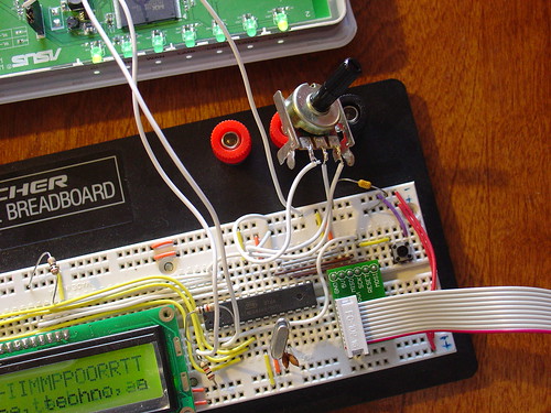
To give you an idea of how this works, here is a demo of the tuner control changing between ten preset stations I have set on the router. The tuner control is in the upper right hand corner of the breadboard. As I adjust the control, the music changes and LCD display updates to show the name of each new station.
Is that cool or what?
If you are interested in adding this functionality to the radio, keep reading and I’ll show you how.
Changes to the hardware:
You will need:
- The completed AVR-based LCD display from part seven
- A 1k-10k trimmer or potentiometer, linear taper
- Some hookup wire
Schematic:
Here is an updated schematic of the AVR circuit showing the potentiometer connected to ADC4 (pin 27).

Firmware:
The AVR firmware has been significantly expanded, slightly reworked and cleaned up in some areas.
The most important changes are:
- The addition of a serial transmit function so the AVR can talk to the router (based on the uart_putchar function)
- New code supporting the analog to digital converter (ADC) which reads the value of a potentiometer connected to ADC4.
- A new Timer1 overflow interrupt has been added, which occurs roughly every 0.5 seconds. The interrupt service routine (ISR) checks the position of the tuner control, and if it has changed, sends the value to the router. The ISR is towards the top of the file, see the SIGNAL (TIMER1_OVF_vect) section.
The ADC range of the ATmega is 0 – 1024 for an input voltage from 0 to 5V. The AVR sends serial data in the format “Tuner: Value” back to the router when the tuner position changes by more than ADC_SENS counts (default is 5). The AVR waits for an “AVR Start!” command from the router before sending any data, this avoids filling up the serial receive buffer on the router before it’s ready to start processing data. An important consequence of this is that the AVR must be reset before running the control script on the router.
You can download the source code and compiled .hex file here. Flash it to the AVR using any compatible ISP programmer and you should be good to go. The source is commented fairly well so if you’re interested in learning how the interface works, take a look. You will need a copy of the ATmega168 datasheet to understand the register names and other architecture-specific parts of the code. Feel free to post in the comments with any questions.
Modifying the circuit:
This part is pretty simple – just wire the potentiometer as shown in the schematic. Most potentiometers have three terminals. The left terminal goes to ground, the right one to +5V, and the middle terminal to ADC4 on the AVR (pin 27).
Tweaks to the OpenWrt configuration:
To make bidirectional communication with the AVR work, we have to change a couple config files on the router and disable some services that would otherwise get in the way.
/etc/config/network
The first change is to modify the /etc/config/network file so that we can always telnet or ssh into the router on a LAN port using the IP 192.168.1.1. The ability to access the router via ethernet is helpful in case we screw something up and lose the wireless connection or the router loses it’s IP address, etc.
Modify the LAN section of /etc/config/network to look like this (changes in bold):
#### LAN configuration
config interface lan
#option type     bridge
option ifname    "eth0.0"
option proto    static
option ipaddr    192.168.1.1
option netmask    255.255.255.0
Save changes, restart the router, and connect an ethernet crossover cable (straight cable might work on some computers) to the router. Configure your desktop/laptop computer with a static IP, like 192.168.1.185. Try to open a telnet connection (or ssh if you have set a password on the router) and see if you can log in. If not, don’t continue with the next steps until you can get this working.
/etc/inittab
We previously used the router’s serial port to get a login shell. Now that we’re trying to receive data from the AVR on the same serial port, we need to disable the login shell or it will capture the data before we can get to it.
Edit /etc/inittab to look like this (changes in bold):
::sysinit:/etc/init.d/rcS S boot
::shutdown:/etc/init.d/rcS K stop
#tts/0::askfirst:/bin/ash --login
#ttyS0::askfirst:/bin/ash --login
tty1::askfirst:/bin/ash --login
/etc/sysctl.conf
Sysrq is a fascinating and very low level debugging feature of the Linux kernel. It can be used to perform troubleshooting operations and reboot the system. Usually it is invoked with a magic key combination on a desktop computer, but in this case I found that it is easy to accidentally trip over the serial port when using an AVR. (The “break” RS-232 code triggers Sysrq, this probably has something to do with it.)
Fortunately, it’s easy to disable by editing the /etc/sysctl.conf file and adding these lines:
# Disables the magic SysRq key
kernel.sysrq = 0
Reboot the router to apply the changes. Now we can get on with the good stuff!
Shell scripting magic:
The real action happens on the router, where a shell script waits for input from the router and changes the station accordingly.
This script is called interface.sh and can be downloaded to the router using wget as shown:
root@OpenWrt:~# cd ~
root@OpenWrt:~# wget http://mightyohm.com/files/wifiradio/interface.sh
...
root@OpenWrt:~# chmod ugo+x interface.sh
The interface script calls an updated version of the display script from part 7, called display2.sh:
root@OpenWrt:~# wget http://mightyohm.com/files/wifiradio/display2.sh
...
root@OpenWrt:~# chmod ugo+x display2.sh
Once both scripts are downloaded, executable and located in /root you can launch interface.sh as follows:
root@OpenWrt:~# ./interface.sh
volume: 60%   repeat: on    random: off
volume: 60%   repeat: on    random: off
adding: http://relay3.slayradio.org:8000/
adding: http://scfire-dtc-aa01.stream.aol.com:80/stream/1046
adding: http://208.101.28.234:8004
… more stations here …
Tuner Position:  0
New station...
http://relay3.slayradio.org:8000/
[playing] #1/10   0:00/0:00 (100%)
volume: 60%   repeat: on    random: off
The interface script adds ten presets to the router, shows the playlist, and then waits for valid tuner data from the AVR. Once it receives a “Tuner: value” line (which should occur shortly after the AVR receives a go signal from the script), the script prints the received tuner positon and changes to the requested station. It will then wait for new tuner data from the AVR and change the station when necessary.
As you can see in the video, this works very well. Over a fast Wi-Fi connection, the time to change stations is almost instantaneous – very satisfying!
That’s it for part eight. In part nine, I’ll add some finishing touches to the router configuration and start talking about enclosures. Stay tuned!
Update: There is a new Wifi Radio Discussion Forum, hop over there to ask questions about the project or see what other people are working on! (4/12/09)
Update 2: Part nine is now available.
show me the code
Hi to everyone
I´ve been trying to finish this project for a long time and I´m stucked in this part. I hope someone could help me.
My question is…in the /etc/sysctl.conf is it necessaty to eliminate everything and add the new lines or just add the new lines without eliminating anything.
Thank you so much
You should add the lines shown and keep the rest.
In the future, please direct your questions to the support forum, it’s easier for me to answer them there!
hi,
I have a problem:
When I telnet the router via the LAN1, then the router doesn’t connect to the wifi network. So I can’t play any music. My settings are:
network
#### LAN configuration
config interface lan
#option type bridge
option ifname “eth0.0”
option proto static
option ipaddr 192.168.1.1
option netmask 255.255.255.0
#### WAN configuration
config interface wan
option ifname “eth0.1”
option proto dhcp
wireless
config wifi-device wl10
option type broadcom
option channel 11
config wifi-iface
option device wl10
option network wan
option mode sta
option ssid netgear
option encryption psk
option key XXXXXXXX
When I change the network settings to
config interface lan
option type bridge
option ifname “eth0.0”
option proto dhcp
#option ipaddr 192.168.1.1
#option netmask 255.255.255.0
then I can’t telnet but I can play music via the terminal
Any ideas on how to make it work via telnet?
Can you post this on the support forums? I’ll take a closer look and see if I can figure out what is going on.
http://mightyohm.com/forum/viewforum.php?f=2
I think the quick answer is to look at part 9, there are some changes to the firewall and network configs there.
I could not make it work correctly, I have even spent some time in the lab at my college but not sure what I have done wrong – thought I could set it up in multi sim and would find my problem but was unable to do so. Thanks for the informations I hope to get it to work soon.
Can you be more specific about what is not working?