Back in March, I released the AVR HV Rescue Shield, my first open source hardware kit. The AVR HV Rescue Shield is a high voltage parallel mode fuse programmer for Atmel AVR microcontrollers.
Since then, I’ve sold dozens of kits around the world.
If you bought a kit, I want to hear from you! Specifically, I’d like feedback on the following items:
Was the kit easy to assemble? Are the assembly instructions clear and easy to follow?
Are you satisfied with the kit? Does it work as advertised?
Have you modified the kit or Arduino sketch in any way, such as adding support for more AVRs or programming modes?
Have you taken advantage of the Open Source Hardware model or CC-licensing to re-use this design in a new and interesting way that you’d like to share?
You can leave feedback in the comments below, or if you want to respond privately, use the contact form to contact me directly.
Matthew Beckler has released a library of electronic component symbols in SVG format, which will make it easy for anyone with the vector drawing program Inkscape to create schematic diagrams quickly and easily. I have been meaning to learn Inkscape for the sole purpose of making prettier schematics, so this library will definitely come in handy.
Matthew says:
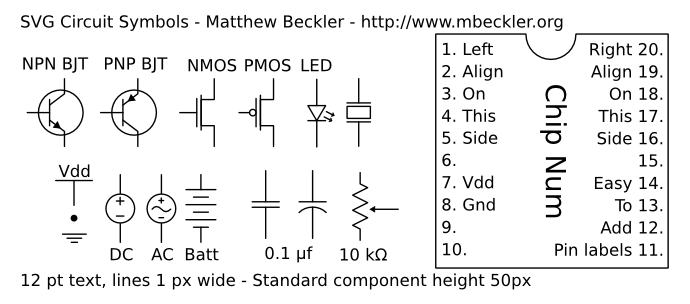
Sometimes you need to create a circuit schematic, but don’t need or want to take the time to do it Right, using a real schematic capture program like OrCad, Eagle, or Kicad. In those situations, I like to use Inkscape to draw circuit schematics. I have collected and standardized the symbols shown below in high-quality SVG format. The components are standardized to have lines 1 pixel wide, 12 pt text, and 50 pixels in length. The IC symbol has pin label text that is easy to customize.
Welcome to Part 3 of the Diamond Chop Saw build. In this installment I’m going to focus on the construction of the mechanical aspects of the saw structure, motor attachment, vacuum chuck, and splash guard. This is a picture-heavy entry…
After thinking for a while about how to build the saw, I decided that it would be best to have the blade move only in the vertical axis, and the workpiece move horizontally in two axes. This led to the overall machine design which consists of a vertical column with pivoting cutting head assembly, and a workpiece holder that has two axes of horizontal motion.
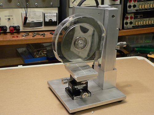
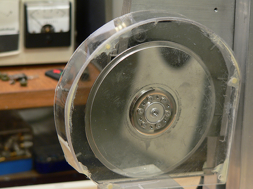
Completed Dicing Saw
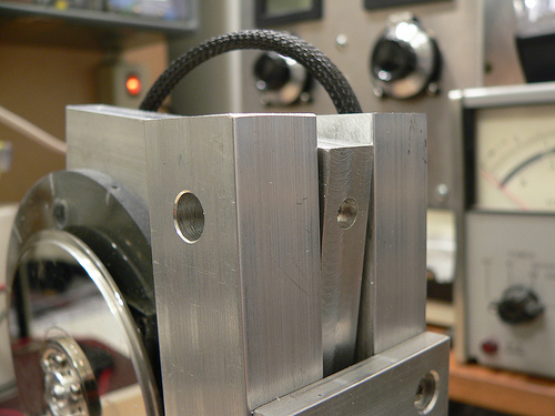
I wanted to ensure the motor and blade had a rigid, heavy mounting structure to reduce effects of vibration and flex on cutting performance. I decided to mount the motor using the original mounting flange from the hard drive enclosure since it was nicely machined to match the motor flange. I used a hacksaw to cut out the shape roughly to size, then straightened up the edges and machined a mounting recess on my milling machine. The L-shaped piece of aluminum is 1/2 inch thick which gives lots of weight and provides sufficient thickness for mounting the bearing while preventing motion orthogonal to the bearing axis.
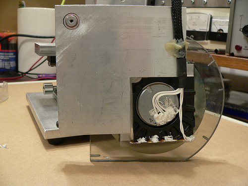
Cutting Head Assembly
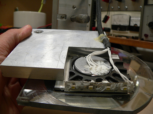
Another view of the cutting head assembly. In the upper left hand corner is the pivot bearing. The bearing is held in place with a set screw that goes through the L-shaped aluminum piece. Along the bottom edge of the black hard drive enclosure portion I attached a strip of white LEDs to help light the work area. RTV Siliconeis used to seal the electrical contacts from water that migt not be caught by the splash shield. At the lower left hand corner of the aluminum plate is a rounded off screw. The cutting depth adjustment micrometer pushes against this rounded off screw. Pushing against the aluminum would be less accurate (aluminum would become unevenly worn).
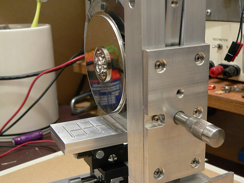
Cutting head assembly (rear view)
At the top of the column on either side is a hole for the screws that hold the pivot bearing (also from a hard drive) in place. Luckily the one I used has 4-40 threaded holes on either side. A screw on each column holds the bearing in place, and then the rest of the column assembly and adjustment plate are attached resulting in a good alignment of the column to the bearing.
Pivot bearing/column mounting detail
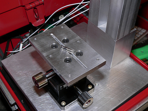
Controlling the depth of the cut is critical, as my cuts will be as small as 5 thousandths of an inch deep! I mounted a micrometer head to a plate on the back of the column which controls the height of the cutting head assembly.
Rear view of the column and depth adjustment control
Now for a little detail on the vacuum chuck… The chuck is made from two 1/4 inch plates of aluminum. The top surface has a shallow set of trenches cut to distribute the suction across the bottom surface of the glass plate used for holding parts. The lower plate has a deep trench cut in it to distribute the suction to the three small holes drilled on the top plate. The whole thing is held together with screws and sealed with silicone. I made a set of hose barbs (one is pictured below) so that I can use 1/8 inch vinyl tubing to connect to my vacuum pump. The barbs were made by turning down 10-32 stainless steel screws on my lathe.
Lower half of vacuum chuck with custom-made hose barb
The last major component of the saw is the splash guard. This actually took a fair amount of effort to make, as I broke pieces more than once and had to start over. Essentially it is a two-piece design with a thick piece screwed to the cutting head assembly, and a thinner piece which screws onto the first. I used a heat gun to soften the plastic and carefully mold it to the shape of the face plates. I then glued the curved section and the outer face plate together using epoxy and while not very pretty, it holds together well.
Splash guard on the saw
That pretty much sums up the mechanical aspects of the saw construction. Next week I’ll post the 4th and final installment which will include alignment and attachment of the blade, and actual use of the saw!
This weekend I am attending the European hacker conference Hacking at Random. HAR takes place every four years at a former socialist youth-camp about an hour away from Amsterdam in the beautiful Netherlands.
Rather than fly directly to HAR, my wife and I decided to make a larger vacation out of our trip, and we have been busy touring Europe for over a week now. We still have over a week left, so expect slow updates until I return and have a chance to catch up!