Update 01/02/09: A PCB version of this circuit is in the design stages – some preliminary information is here.
Update 03/11/09: Kits based on this design are now for sale!
Update 12/14/10: The original AVR HV Rescue Shield kit has been replaced by the new and improved HV Rescue Shield 2. Visit the HV Rescue Shield 2 product page for information about the new kit!
As I mentioned earlier this week, I recently “lost” an ATmega168 due to flashing the configuration fuses to disable the RESET pin, without realizing that this makes the device impossible to reflash with SPI. This is particularly frustrating because the device is still 100% functional, just completely deaf to ordinary serial programmers. The only way to recover the device is using what Atmel calls “High Voltage Parallel Programming Mode” which very few programmers support, most importantly, not the USBtinyISP I otherwise love.
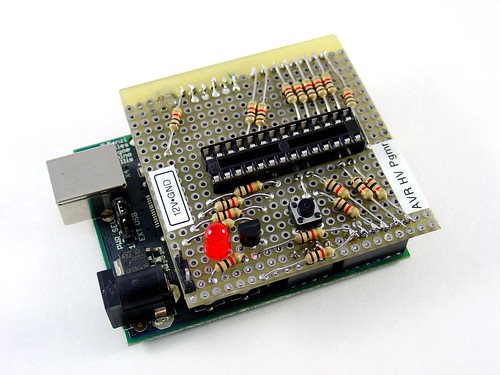
Fortunately, my trusty Arduino came to the rescue – I created an Arduino-based AVR programmer that uses the high voltage programming mode and can fix pesky fuses like RSTDISBL.
The Arduino has just enough IO to implement the entire HV protocol plus a “go” button. So far I have only implemented setting LFUSE and HFUSE in software, but there is no reason why the code couldn’t be extended to support chip erase and programming the entire flash as well.
Overview:
The fuse programming process is simple:
- Upload the HVFuse sketch to the Arduino, available for download here: HVFuse.pde
- Install the shield and apply +12VDC to the terminals on the left
- Wait for the red LED to turn on (if it isn’t already)
- Install the ATmega to be repaired
- Push the button
- As soon as the LED turns back on, the AVR is fixed and ready to be put back into service!
Schematic:
Here is an Eagle schematic of the HV Programming shield (click to enlarge):
Update 12/17/08: An observant reader pointed out that there were three errors in the way GND/AGND, AREF and VCC/AVCC were connected on the target AVR in the original schematic. The errors have been fixed and the updated schematic is below. Apologies for any confusion this caused.

Parts list:
- An Arduino NG, Diecimila, or compatible
- A piece of perfboard cut to size
- Header pins for the Arduino interface (note I had to drill some of the holes to get the headers to fit the nonstandard pin spacing for digital lines 8-13.
- An LED which indicates when it is ok to insert/remove the AVR
- A 2N3903 or similar NPN transistor (2N2222, etc.)
- (20) 1k resistors – these protect the Arduino from short circuits in case something goes wrong
- A pushbutton switch – this is the ‘go’ button
- A 28 pin socket for the target AVR
Kits!
A kit version of this project is available. Visit the HV Rescue Shield 2 product page for more information.