
Update 01/02/09: A PCB version of this circuit is in the design stages – some preliminary information is here.
Update 03/11/09: Kits based on this design are now for sale!
Update 12/14/10: The original AVR HV Rescue Shield kit has been replaced by the new and improved HV Rescue Shield 2. Visit the HV Rescue Shield 2 product page for information about the new kit!
As I mentioned earlier this week, I recently “lost” an ATmega168 due to flashing the configuration fuses to disable the RESET pin, without realizing that this makes the device impossible to reflash with SPI. This is particularly frustrating because the device is still 100% functional, just completely deaf to ordinary serial programmers. The only way to recover the device is using what Atmel calls “High Voltage Parallel Programming Mode” which very few programmers support, most importantly, not the USBtinyISP I otherwise love.
Fortunately, my trusty Arduino came to the rescue – I created an Arduino-based AVR programmer that uses the high voltage programming mode and can fix pesky fuses like RSTDISBL.
The Arduino has just enough IO to implement the entire HV protocol plus a “go” button. So far I have only implemented setting LFUSE and HFUSE in software, but there is no reason why the code couldn’t be extended to support chip erase and programming the entire flash as well.
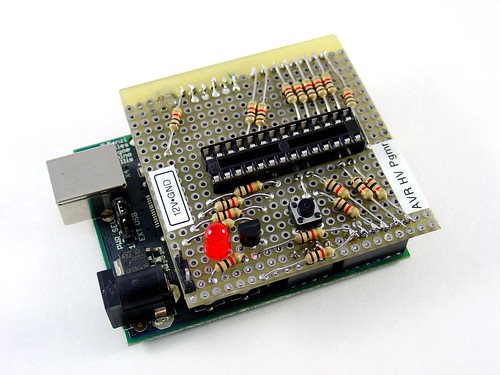
Overview:
The fuse programming process is simple:
- Upload the HVFuse sketch to the Arduino, available for download here: HVFuse.pde
- Install the shield and apply +12VDC to the terminals on the left
- Wait for the red LED to turn on (if it isn’t already)
- Install the ATmega to be repaired
- Push the button
- As soon as the LED turns back on, the AVR is fixed and ready to be put back into service!
Schematic:
Here is an Eagle schematic of the HV Programming shield (click to enlarge):
Update 12/17/08: An observant reader pointed out that there were three errors in the way GND/AGND, AREF and VCC/AVCC were connected on the target AVR in the original schematic. The errors have been fixed and the updated schematic is below. Apologies for any confusion this caused.

Parts list:
- An Arduino NG, Diecimila, or compatible
- A piece of perfboard cut to size
- Header pins for the Arduino interface (note I had to drill some of the holes to get the headers to fit the nonstandard pin spacing for digital lines 8-13.
- An LED which indicates when it is ok to insert/remove the AVR
- A 2N3903 or similar NPN transistor (2N2222, etc.)
- (20) 1k resistors – these protect the Arduino from short circuits in case something goes wrong
- A pushbutton switch – this is the ‘go’ button
- A 28 pin socket for the target AVR
Kits!
A kit version of this project is available. Visit the HV Rescue Shield 2 product page for more information.
That’s correct!
Yeah that was a little confusing, but I have pin 8 on the target going GND on the atmega168, and I have 7, 21, 22 (not 20) all wired together.
The positive high on the atmega168 (arduino) should be +5vdc correct?
Assuming the AVR isn’t blown this will fix any LFUSE and HFUSE combination. HV programming doesn’t require a working clock source so this should fix your chip. Double check all of your wiring connections and maybe try swapping out the transistor for another one.
Also, another reader pointed out that the schematic is slightly confusing – pin 8 of the target AVR is not connected to pins 22, 21, etc. Pin 8 crosses over the wire for those pins (there is no dot at the intersection) and goes to GND on the Arduino.
Another troubleshooting tip – if you insert long delays (a few seconds) into the Arduino sketch at various points you can use a DMM to check if the voltages to the AVR are toggling correctly. This helps you verify that A. the sketch is running and B. the wiring to the AVR is correct.
The fuses I actually changed on my “locked” atmega8 are I programmed CKOPT, and I set the clock source to external low frequency something or other. I was experimenting with a 16MHz crystal for the first time. Will this device reset the mega8 back to factory or does it just do the resetdisbl and spien fix?
Still locked out… 🙁
It will probably work – only one way to find out!
OK, I’m a newb, I had my NPN backwards. Now its working properly, but I can only get 11.86 out of my LM7812. Will it program with less than 12v?
2N3904 is fine. In fact, almost any small signal NPN transistor should work.
Oh, I forgot to mention, Radio Shack didn’t have a 2N3903, only a 2N3904 which I purchased. Me not knowing enough about this sort of thing, I am not sure what difference it would make if any..
Ok, two things:
1. The target AVR draws very little current from the 12V supply when it’s programmed, so the voltage drop across the 1k resistor is negligible.
2. The transistor is set up in an inverting configuration. When the transistor is on, the voltage to the AVR is close to 0V. When it’s off, the voltage swings up to 12V. So to put the target AVR into programming mode, the transistor is turned off by pulling the base resistor LOW.
The LED sounds like it’s working correctly. It doesn’t take long to program the fuses. The LED is a “Ready” light, it turns off during programming and turns on when it’s safe to insert/remove the AVR.
So i’m confused. Don’t you want the reset pin on the bad atmega to receive exactly 12volts? If you input exactly 12 volts into this circuit, wont the 1k resistor drop the voltage? as well as some voltage lost in the transistor?
Just a few more things…
I’m not using an Arduino, Just simply an ATmega168 to fix a bad ATmega8. I changed the LFUSE and HFUSE definitions to use the mega8 hex addresses in the code, and then compiled it and used AVR Studio 4 to upload the hex to my mega168. I then “translated” the schematic to just using a mega168 rather than an Arduino with those cryptic pin names.
Was there anything else in the code I have to change besides the fuse definitions at the top?
So, besides the code in question, and the voltage at the reset pin being too low…The LED lights up, I push the button, the LED goes out, wait about 10 seconds, and the LED light back up!
Brandt –
I’m using a lab power supply that I had handy, but any low current well regulated 12V supply should work. The RESET pin draws very little current, certainly less than a few mA.
Does the voltage drop to 7.66V even when the target AVR is removed? Do any components on the Arduino or the programmer get hot?
Check the wiring of your transistor and try to get the 12V switching circuit working without an AVR first, then test with a target AVR installed and see if it still woks.
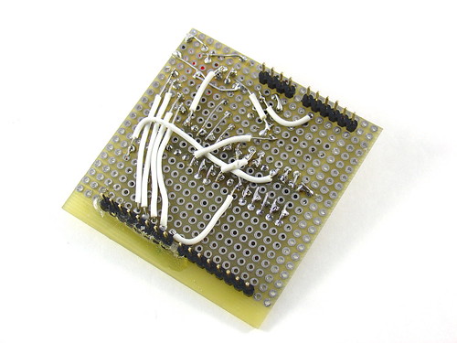
Here is a picture
What are you guys using for a 12vdc source? I am using a 15vdc 3a laptop power supply, through a 12v regulator, but the reset pin is only getting ~7.66v when I push the button.
Gabriel – It’s not in the code, but it could be added pretty easily. Right now only HFUSE and LFUSE are actually implemented.
This is so cool!!! I have a mega8 with a bad signature, but other than that I can use uisp to force program it, but can’t use avrdude or any other loader that verifies signature. I think it is in the Efuse? Can your program reset the Efuse as well as the Hfuse and Lfuse?
Yeah, i know… you waste a perfectly good chip because you messed up the fuses… not gonna happen anymore. I liked this thing so much, i made a PCB design in eagle cad. email me if you want a copy of it for production or distribution. keen101 [at] gmail [dot] com
Thanks! I just can’t see throwing away a perfectly good AVR because of the fuse settings. This programmer also works if you flash the clock settings to something weird because it doesn’t require a working clock source to function (unlike ISP mode).
Yeah! Thanks so much. I’ve been looking for a cheap/simple one of these for months.
I built one today, and it worked! It fixed my “broken” mega8 today. Yeah! 😀
You deserve an award for this. Keep em coming!
That’s absolutely right. It’s already been done for the more common ISP programming mode, see here:
http://www.arduino.cc/cgi-bin/yabb2/YaBB.pl?num=1165363464/6
Quote: “So far I have only implemented setting LFUSE and HFUSE in software, but there is no reason why the code couldn’t be extended to support chip erase and programming the entire flash as well.”
Are you actually saying that you can turn Arduino to a full blown AVR prgrammer? Is that right?
I am really really interested in that. I am trying to solve chicken-and-egg problem and build a AVR programmer, because I haven’t got one. So this would be a great help.
“Do you think there would be a market for a version that only supported the 48/88/etc series?”
I think there is. I will be one of those.
Thanks for sharing.
How about two rows of jumpers – one for the AT tiny – and another for the AT mega? it you really wanted to get fancy dip switches… Cheap and to the point
JD,
ZIF socket – that’s a great idea. What I haven’t figured out yet is how to make it pin compatible for more than just the ATmega48/88/168/328 series. It may work for some other 28 pin MCUs but almost certainly not for any other family, like the ATtiny’s. It would be nice if the same board could be used for multiple families of parts. Do you think there would be a market for a version that only supported the 48/88/etc series? I’m not looking to make money, just to recover the costs of the PCB run.
Jeff,
That would make a nice daughter board for Arduino et al. Why don’t you design one with a zif socket and a professionally manufactured board/kit? This design is simple enough that with careful layout you could probably get away with a single sided board with soldermask.
I’m not an expert at protoboard either! The back is definitely the ugly side. I started out pretty neat and organized but by the end I was pretty much throwing wires on. 🙂
http://www.flickr.com/photos/mightyohm/2887867387/
That’s awesome. I’ve been wanting something like this. With a 12V step-up regulator, it would be complete.
Would you mind taking a photo of the bottom of the protoboard? I’ve never been good at protoboard, and I’d really like to see what other people’s look like..