This is the second part of an ongoing series about building a low cost, open source streaming internet radio. if you haven’t already, check out part one for some background about the project.
Onward…
In part one, I discussed the merits of streaming internet radio and the motivations for my Wifi Radio project. Now it’s time to start looking at what hardware can make this project a reality. Before we get started, let’s review the requirements list from last time.
Requirements:
- Wireless connectivity through existing Wifi network
- Audio output (preferably 44kHz, 16 bit stereo)
- An integrated amplifier and speaker(s)
- Shoutcast/MP3 streaming audio decode
- Several builtin station presets
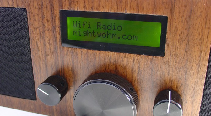
- A display to indicate the station and currently playing song
- Simple user interface, using standard radio controls (volume, tune, etc)
- 110VAC operation
There are two additional requirements that I implied in the first post but forgot to include explicitly:
- Cheap, priced below a commercial streaming radio – target < $100.
- Small size so it can be portable (no desktop PC’s allowed!)
Selecting the hardware:
How do these requirements translate into hardware? Let’s take a stab at what features we’d like in an embedded platform.
- A wireless interface
- Audio output
- Sufficient system resources (CPU, memory, etc.) to decode MP3s
- Some extra IO for a control panel and display
- Low cost
- Small size
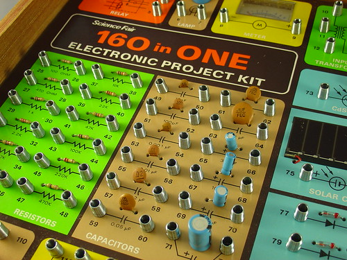
- Ease of development
The size and cost aspects pushed me towards an embedded system instead of a small form factor PC like any of Shuttle’s XPC offerings or a nano-ITX board. To me, “Ease of development” equals Linux, so I wanted something well supported by Linux and an active open source development community.
There are quite a few embedded Linux platforms out there, with a wide variety of prices and features. I looked at a few of them, including:

- The Tin Can Tools Hammer – very impressive ARM9-based board with USB, lots of RAM and flash, lots of IO, and best of all the footprint of a 40-pin DIP package (breadboard compatible!). No wireless and relatively steep pricetag ($160).
- TI‘s Beagle Board – Incredible featureset including DVI output and a 600MHz ARM Cortex core. No wireless and price is stunning for what you get, but overkill for this project ($150). (Must keep in mind for future projects!)

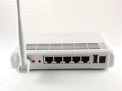
- Consumer wireless routers like the Asus WL-500gP v2 and WL-520GU – builtin wireless (yay!), USB, 240MHz Broadcom 5354 core, decent RAM and flash, cheap. Newegg has the WL-520GU for an incredible $26 after rebate
(normally $50). The higher end WL-500g has more memory and flash and an integrated USB 2.0 hub (2 external ports). Newegg has the WL-500g Premium V2
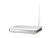
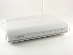
Tiny, under $50 and with built-in wireless, the Asus WL-520GU is the clear winner for this project. The downside? Since this router was never intended to do anything other than, well, route, we’re going to have to crack it open, modify it, and void the warranty. In addition, there is no tech support and we’re going to have to spend some extra time hacking around to get it to do what we want.
Here it is in all it’s glory:
Here’s a sneak peak of the inside:
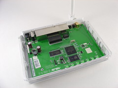
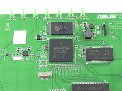
This router is supported by OpenWRT, an open source Linux distribution for small embedded devices. Ignore the work-in-progress designation, it works, trust me!
Although the router lacks builtin audio, that is easily solved with an $8 SYBA SD-CM-UAUD USB Stereo Audio Adapter. There have been reports that the WL-520GU only supports USB 1.1 reliably, but USB audio doesn’t require USB 2.0 so it’s not an issue for us. For full USB 2.0 support, look at the WL-500gP v2 instead.
So far we have $58 into the project ($38 if you are lucky enough to get the rebate) and we have an embedded Linux computer, a wireless interface, and an audio output. Not bad!
That’s it for part two! In part three I’ll install a serial port on the router and get ready to reflash the stock firmware with OpenWrt. At that point we’ll be able to start listening to some tunes!
Update: I posted detailed specs for the WL-520GU and a couple more photos here.
Update 2: I posted some images of the $8 USB-Audio Adapter I am using as well.
Update 3: Part three is now available.
Update 4: There is a new Wifi Radio Discussion Forum, hop over there to ask questions about the project or see what other people are working on! (4/12/09)