Tag Archives: featured

The greatest electronics book ever written?

Getting Started in Electrionics, by Forrest M. Mims, III

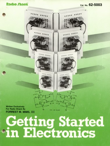
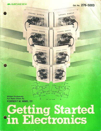
Getting Started in Electronics, by Forrest M. Mims, III. is a spectacular introduction to the world of electronics.  This book is not new – the truth is that it has changed little since it’s first release in 1983.  Despite this, twenty-five years later, there is really nothing else like it.  This book is suitable for beginners of any age yet it comprehensively describes the technical theory and practical use of electronic devices like resistors, capacitors, inductors, diodes, transistors, FETs (including the now-rare JFET), and LEDs, as well as circuits like amplifiers, oscillators, and logic gates.  There is even a graphical introduction to device physics (semiconductor materials, doping, electrons and holes) and semiconductor fabrication!  This is kind of stuff they teach third-year students in university ECE classes, written in a way that is understandable to a child in third grade!

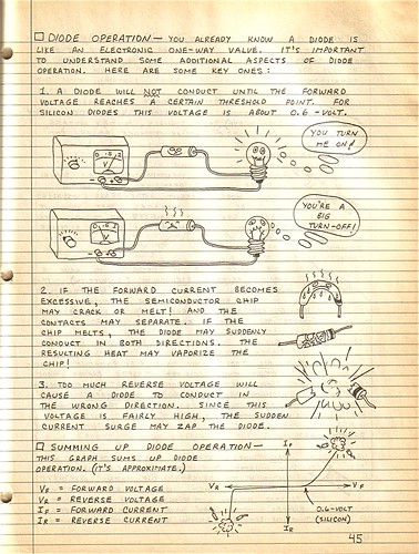
The entire book is formatted like an engineering notebook with handwritten notes on every page.  The illustrations are fun and make the book friendly and accessible.    Here is an excerpt from the chapter on diodes:

Getting Started in Electrionics, by Forrest M. Mims, III

My father gave me this book when I was six or seven years old along with a 25 watt soldering iron from Radio Shack.  I am convinced that this book, together with a Science Fair 160-in-ONE kit, is what caused me to pursue a career in Electrical Engineering.  I still enjoy leafing through its pages and proving to myself that I can understand how each circuit works.

Forrest Mims himself is an interesting individual and has led a prolific career as a writer and amateur scientist.  He is an active member of the Society for Amateur Scientists (SAS) and edits the Citizen Scientist.

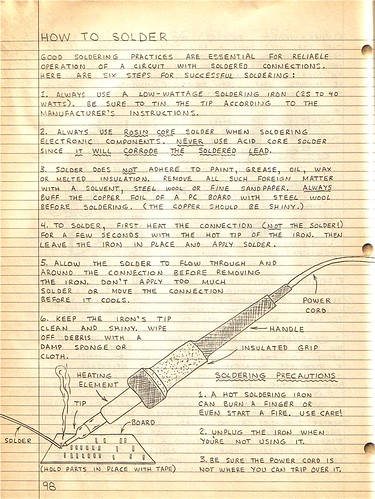
The book even includes a handy guide to help you learn How to Solder!

Getting Started in Electrionics, by Forrest M. Mims, III

Thankfully, it turns out that this fantastic book is still in print. The groovy green cover is gone (a mistake, in my opinion), but the contents have not changed.  This is fantastic news for anyone interested in learning about electronics.  These also make great Christmas presents – I bought one for my brother last year and he loved it!

In my opinion, this is probably the greatest introductory book about electronics ever written.  I’d be curious to hear if anyone has any other favorites – leave a comment if you do!

Happy 25th, Getting Started in Electronics!

Bluetooth Handset Hack

Bluetooth Handset Hack

Kylie recently gave me an old, broken Motorola HS820 bluetooth headset.  The headset suffered from a defective microphone that resulted in extremely low volume on outgoing audio, even though everything else worked fine.

Upon receiving it, I proceeded to rip the headset apart, interested to see what was inside.  I found a fairly simple PCB with a discrete bluetooth module in the center.  The PCB is not labeled, but given that this is an older headset (3-4 years old) most of the connections are large enough to attack with a pencil iron and solder wires to.

This headset was begging for a project.

Motorola HS-820 PCB - Back

On my last trip to Weird Stuff, I came across the beauty shown below.  The instant I saw it (and three other boxes full of others like it) I knew exactly what I was going to do with the broken headset: make it into a Bluetooth Handset instead.

Shown below is a vintage International Telephone & Telegraph telephone handset.  ITT manufactured phones in the 60s and 70s;  later they spun off that part of the business to Alcatel and then got into some trouble with the government in 2007.

Vintage ITT Telephone Handset

The handset has some heft to it and feels great to use.  It is amazing how accustomed we have become to using extremely ergonomically poor cellphones.  Just compare the shape and size of a modern cellphone to a handset like this and you can understand why it is so refreshing to pick up and use one of these.

They don’t make them like this anymore.  Unscrewing the faceplates reveals a speaker and a microphone which falls out onto the floor if you’re not careful.  I remember phones like this when I was very young but hadn’t seen one in years.

Vintage ITT Telephone Handset

Sticking the guts of the HS820 into the handset was not that difficult or time consuming.  The speaker works as-is.  It turns out the impedance of the speaker that came with the bluetooth headset is around 30 ohms, while the vintage handset speaker is 42 ohms, close enough.  The audio quality is excellent!

The original microphone on the HS820 was an electret, which is not the same as the carbon style on the handset.  Despite this, I was able to get the microphone on the handset to work by adding a 1k series resistor and wiring it to the same terminals on the headset as the original.  Without the resistor, my voice was too loud and distorted.  The value took some experimentation and I may continue to play with it, or eventually give up and install a modern electret style mic instead (but the original is just too cool).

I added a pushbutton to replace the multifunction button on the headset.  Holding down this button turns the handset on and off.  Pushing it answers calls and probably does other stuff that I haven’t played with.  The headset has volume buttons too, but the volume can be controlled via software so I didn’t wire them up to anything.

Pushbutton

I also added a charging jack where the cord originally was.  The washer is needed to fill the relatively large opening for the cord.

Charging jack

A ridiculously bright blue LED is wired in place of the status LED on the headset.  I found the LED holder in my junk box.

Bluetooth Handset Hack

This shows the connections for the pushbutton (yellow and green wires in the center) and the LED (red and black in the bottom center).  I removed the original pusbutton with my hot air rework station and soldered the new wires in place, then put a dab of hot glue on top to keep them in place.  The big blue thing in the middle is the bluetooth module.  I imagine that modern headsets do not have a discrete PCB for this.  The HS820 PCB tucks inside the center of the handset when installed and stays in place without any special mounting.

Bluetooth Handset Hack

The other side of the HS820 PCB shows the 3.7V lithium battery and the connections for the microphone (lower left), speaker (lower right) and charger (upper right).  The battery is glued to the PCB.

Bluetooth Handset Hack

I modified the Motorola charger that came with the headset by cutting off the original 3 pin plug and replacing it with a 4.7mm power connector to match the jack on the phone.  The third pin of the original connector wasn’t being used anyway.

Bluetooth Handset Charger

To charge the handset, you just plug in the charger.  The LED lights up to show that the handset is charging and goes out when it’s done.  It flashes during normal use, blinding spectators.

Charging

I’m planning to use this for Skype on my desktop computer, but I may just have to carry it around for a few days to see what other people think of it…

Update: As mentioned in the comments, these are for sale at ThinkGeek.com, search for “retro handset”.

Update 2 (11/20/09): Welcome, Make: readers!  Questions about this project?  Head over to the forums for help!

Building a Wifi Radio – Part 1, Introduction

This article is the first of a series that will document the development of a low cost, open source wireless streaming internet radio receiver.  All construction details, including schematics, source code, and even the design process itself will be documented on this blog.

Comments and (constructive) criticism are welcome. Click here to post a comment.

Table of Contents:

  1. Building a Wifi Radio – Part 1, Introduction (you are here)
  2. Building a Wifi Radio – Part 2, Choosing an Embedded Platform
  3. Building a Wifi Radio – Part 3, Hacking the Asus WL-520GU
  4. Building a Wifi Radio – Part 4, Installing OpenWrt
  5. Building a Wifi Radio – Part 5, Let’s Make Some Noise!
  6. Building a Wifi Radio – Part 6, A Conversation with Mpd
  7. Building a Wifi Radio – Part 7, Building an LCD Display
  8. Building a Wifi Radio – Part 8, Adding a Tuning Control
  9. Building a Wifi Radio – Part 9, A Few Odds and Ends
  10. Building a Wifi Radio – Part 10, Building the Box

Some background:

According to Wikipedia, in 1993 the first internet radio program began distribution.  At that time, radio programs were manually downloaded to be played later on the user’s home computer; the user experience was far from that of listening to a traditional broadcast radio receiver.  It was not until several years later that streaming radio became common, giving birth to internet radio stations that could be listened to much like traditional radio, but with several advantages.  Most notably, internet radio stations were (and still are for the most part) largely devoid of on-air advertising, and stations anywhere on the globe could be received by anyone with access to the internet.  Over time, improvements in audio compression (such as MP3) and larger end user bandwidth improved the fidelity and reliability of internet radio.  The birth of common standards like Shoutcast made it possible to listen to many stations with a single player program, like Winamp.

Today, most music playback software supports streaming radio in some way.  iTunes features thousands of streaming radio stations and even supports Shoutcast streams so that users can easily add additional stations of their own.

The beautiful thing about streaming radio is the huge diversity in programming that is available.  Many college radio stations have a streaming server, like KDVSDigitally Imported hosts many electronic and dance music streams that give the listener the choice to listen to specific genres like ambient or gabber hardcore (whoa).  Broadcast radio usually lumps all electronic dance music into one category, much to the dismay of their listeners (who probably tuned out during the commercial break, anyway).  Gems like Slay Radio specialize in music you would never hear on broadcast FM, like Commodore 64 remixes.

In the past couple years, products have started to appear that mimic the form and function of a traditional radio, but play internet radio instead.  Good examples of these are the Roku SoundbridgeRadio and the ASUS Internet Air.  Remote speaker devices, such as the Apple Airport Express, require a PC to receive and relay streaming radio but achieve a similar end result (but don’t really look much like a radio).

The Wifi Radio project:

I have been wanting to build a streaming radio for some time.  I frequently work in my garage, where I occasionally use my Macbook to play music through a small amplifier and bookshelf speakers.  The problem is that my laptop is not always set up in the garage, and greasy fingers are not a good thing to have around a white laptop, period.  I could simply buy an internet radio, but I couldn’t stomach the $150-$300 price tag on most players for such a luxury.

So I decided to build one instead.

I started the design process by drafting an outline of desired features, and then breaking them down into wants and needs, while trying to keep the project scope under control.

Requirements:

  • Wireless connectivity through existing Wifi network
  • Audio output (preferably 44kHz, 16 bit stereo)
  • An integrated amplifier and speaker(s)
  • Shoutcast/MP3 streaming audio decode
  • Several builtin station presets
  • A display to indicate the station and currently playing song
  • Simple user interface, using standard radio controls (volume, tune, etc)
  • 110VAC operation

Optional features:

  • Line output (to connect to a receiver/amplifier)
  • Web server for configuration/management
  • Ability to play files off a USB stick or iTunes server

Definitely won’t be a feature:

  • Any kind of over-the-air radio tuner
  • Commercials
  • Pledge season
  • Morning DJ’s
  • “Blah, blah, blah.”

Now that we’ve defined the project…  it’s time for a commercial break.  That’s it for part 1 of this series.  Stay tuned for part 2, where I’ll talk about choosing an embedded platform for the design and why Linux is so awesome!

Update: Part two is now available, click here to see it!

Update 2: There is a new Wifi Radio Discussion Forum, hop over there to ask questions about the project or see what other people are working on!  (4/12/09)

Update 3 (6/1/09): I finally added a table of contents to the top of this post to help everyone (including me) navigate the series!

Arduino-based AVR High Voltage Programmer

Arduino-based AVR High Voltage Programmer

Update 01/02/09: A PCB version of this circuit is in the design stages – some preliminary information is here.

Update 03/11/09: Kits based on this design are now for sale!

Update 12/14/10: The original AVR HV Rescue Shield kit has been replaced by the new and improved HV Rescue Shield 2.  Visit the HV Rescue Shield 2 product page for information about the new kit!

As I mentioned earlier this week, I recently “lost” an ATmega168 due to flashing the configuration fuses to disable the RESET pin, without realizing that this makes the device impossible to reflash with SPI.  This is particularly frustrating because the device is still 100% functional, just completely deaf to ordinary serial programmers.  The only way to recover the device is using what Atmel calls “High Voltage Parallel Programming Mode” which very few programmers support, most importantly, not the USBtinyISP I otherwise love.

Fortunately, my trusty Arduino came to the rescue – I created an Arduino-based AVR programmer that uses the high voltage programming mode and can fix pesky fuses like RSTDISBL.

The Arduino has just enough IO to implement the entire HV protocol plus a “go” button.  So far I have only implemented setting LFUSE and HFUSE in software, but there is no reason why the code couldn’t be extended to support chip erase and programming the entire flash as well.

Overview:

The fuse programming process is simple:

  • Upload the HVFuse sketch to the Arduino, available for download here: HVFuse.pde
  • Install the shield and apply +12VDC to the terminals on the left
  • Wait for the red LED to turn on (if it isn’t already)
  • Install the ATmega to be repaired
  • Push the button
  • As soon as the LED turns back on, the AVR is fixed and ready to be put back into service!

Schematic:

Here is an Eagle schematic of the HV Programming shield (click to enlarge):

Update 12/17/08:  An observant reader pointed out that there were three errors in the way GND/AGND, AREF and VCC/AVCC were connected on the target AVR in the original schematic.  The errors have been fixed and the updated schematic is below.  Apologies for any confusion this caused.

hvfuse_fixed.sch

Parts list:

  • An Arduino NG, Diecimila, or compatible
  • A piece of perfboard cut to size
  • Header pins for the Arduino interface (note I had to drill some of the holes to get the headers to fit the nonstandard pin spacing for digital lines 8-13.
  • An LED which indicates when it is ok to insert/remove the AVR
  • A 2N3903 or similar NPN transistor (2N2222, etc.)
  • (20) 1k resistors – these protect the Arduino from short circuits in case something goes wrong
  • A pushbutton switch – this is the ‘go’ button
  • A 28 pin socket for the target AVR

Kits!

A kit version of this project is available.  Visit the HV Rescue Shield 2 product page for more information.