Gary Dion (N4TXI) created a Wifi Radio to match his entertainment center. His project is inspired by my original Wifi Radio project and shares several of the same parts (such as the Asus WL-520gU wireless router) and design philosophy.
Interesting features of Gary’s version of the radio:
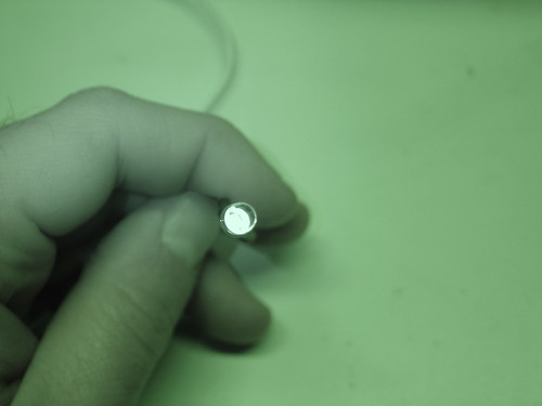
Very cool 4 line VFD display allows more information to be shown at once (and it’s blue!)
AVR sends actual shell commands to the router, which allows the serial console to remain enabled for debugging/other purposes – brilliant!
Nice custom PCB for the ATmega8 microcontroller
Rotary encoder and significantly more advanced control menus
IR remote control support!
More details, photos, and source code are available on Gary’s site.
Thanks to the Make: blog for bringing this project to my attention!
Finally, I bring you the conclusion of my Diamond Chop Saw series!
In this part I’ll cover a few remaining issues, but mostly I’ll report on my use of the machine in the construction of my 47 GHz radio, for which this project was intended. If you’re not already familiar with this project, you might want to go back and start by reading Part 1.
Attaching/Aligning the Blade
Attachment of the blade to the hard disk platters (see part 2) sets the basic accuracy of the tool. If the blade is out of plane the cut will be wider than the blade. If the blade is off center, portions of the blade will wear faster. Achieving perfection is virtually impossible, but I managed to get a ‘good enough’ result.
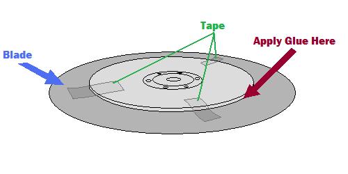
My method was to lay the ring blade down onto the larger platter and use tape to temporarily hold the blade in place while I manually spun it around to check for centering.
Method for centering the blade
A little fiddling and re-alignment will get things pretty close. After the centering is good, the next step is to glue the blade into place. I used tiny drops of Zap-a-Gap around the inner edge of the ring and held the two together firmly as the glue set.
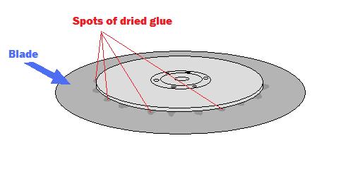
After gluding the blade, spots of glue are visible on the top surface
The result is not perfect, but cuts I have done seem to be sufficiently narrow.
The Cutting Setup
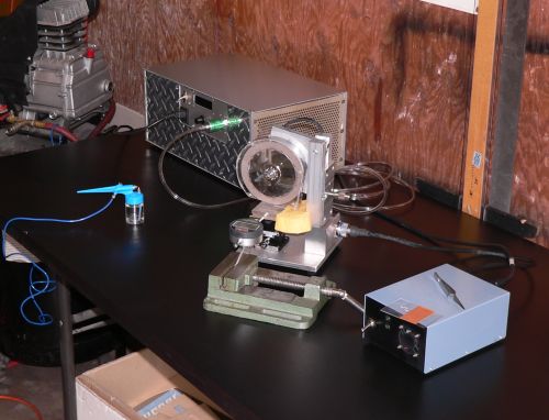
The picture below shows the setup for making cuts. The large silver box in the background is the vacuum pump, the green vise in front is holding a digital indicator (for making precisely measured cuts) and the blue airbrush is ready for spraying water onto the cutting surface.
Dicing saw setup
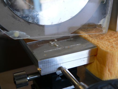
The parts to be cut are mounted on glass slides using Crystalbond adhesive, a thermoplastic mounting polymer.
Test substrates about to be cut
Using the Chop Saw
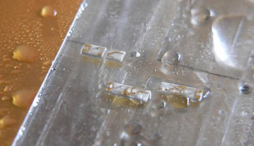
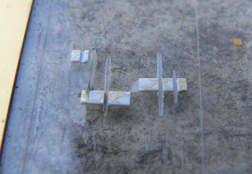
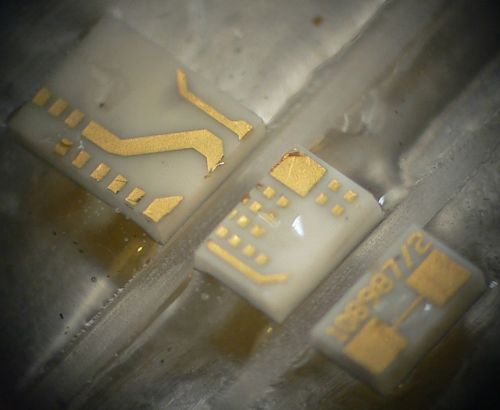
Below are some pictures of cuts made with the saw.
A partial cut through one of the substratesSeveral diced pieces. Microscope view of a part diced into three pieces
From the photos above it is clear that the saw is working reasonably well. The cuts are straight, the pieces have no obvious large chunks missing, and the gold metallization shows minimal signs of peeling. I have made many cuts using this saw including angled cuts. I have also used the saw to carefully strip off the backside metallization. This will come in handy when I am making diveboard-style waveguide transitions. I have also used the X/Y table to feed the piece along the blade, allowing me to make much longer cuts than in “chop” mode. These came out very nicely as well.
The accuracy of the saw is reasonably good. Using a dial or digital indicator, cuts can easily be made with 0.001 inch accuracy, which is sufficient for circuits working through 50 GHz at least.
One issue that was of concern initially was whether a hard drive motor actually had enough power to do the job. It turns out the motor works fine as long as the cuts are made slowly. Fast cuts are not advisable anyway, as the part is more likely to fly off into oblivion. Some of the substrates I cut had fairly thick metal backing and required slower cuts.
Future Improvements
Every project ends up with room for improvement. With this project a few things come to mind including a precision machined spindle with a better mounting mechanism. This would require a much larger lathe than what I own, and some careful though into balancing. Another improvement would be a self-contained coolant sprayer and vacuum pump for the chuck. Setting up the dicing saw currently requires a vacuum pump, an air compressor, and so on. Another nice feature would be a microscopic camera to observe the cutting in action. And finally a CNC retrofit would be nice. All of these upgrades would be handy, but as it is, the saw is immensely flexible and precise. I’m still on the first blade which is showing no signs of wear.
Conclusion
It has been a lot of fun putting together this series of articles and even more fun putting together and using this saw. So if you are planning on putting together a saw like this, happy cutting! If you are just planning on building something with a hard drive motor, they are really handy for certain applications where high precision, high RPMs, and cheapness are required.
Wow, 2010 came a lot quicker than I expected! With one day to spare, here’s a brief look back at some of the highlights of 2009 here at mightyohm.com.
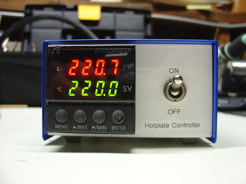
DIY PID-Controlled Soldering Hotplate:
I needed a hotplate for surface mount soldering, so I built one from scratch using a milled block of aluminum, a 500W cartridge heater, and a surplus PID controller. Some of my favorite DIY projects have been building my own tools, and this one is a great example.
The AVR HV Rescue Shield:
This year saw the release of my first electronics kit, the AVR HV Rescue Shield. Designed in response to my own experience accidentally setting the RSTDISBL fuse on an AVR microcontroller, the AVR HV Rescue Shield has helped many microcontroller enthusiasts around the world rescue their otherwise crippled, stuck, or deaf AVR’s.
In April I flew out to Cleveland and gave a talk about Hacking the Asus WL-520gU Wireless Router at Notacon 6. The con was a huge amount of fun but reminded me just how much work it is to give a talk. I met lots of cool people there, including George Sanger and Jeri Ellsworth, aka The Fatman and Circuit Girl.
By the way, the submission deadline for talks at Notacon 7 closes on January 31st!
DIY TiVo IR Blaster:
My DIY TiVo IR Blaster was a simple hack constructed in an hour entirely out of parts I already had in the lab. The best part is that eight months later, it’s still working flawlessly. Like any good hack, this one is cheap, simple, and just works.
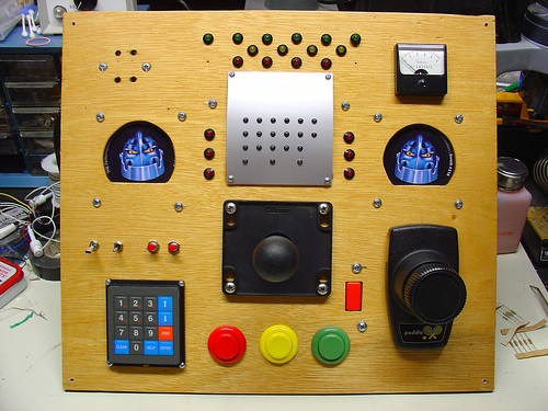
Harrison’s Box:
This project, codenamed “Harrison’s Box“, was a collaboration with my wife Kylie and my father-in-law Bill to build an “electronic box” to give to my nephew Harrison’s on his first birthday. We added as many switches, knobs, and lights as we could. Harrison loved it!
Those are some of the highlights of 2009. I hope to bring more cool projects, hacks, and kits to you in 2010!
Lastly, Happy New Year and a sincere thanks to everyone who has been reading the blog, leaving comments, buying kits, or supporting the site in some way over the past year!
The seminar was led by LTspice author and advocate Mike Engelhardt. For someone like me who has never used LTspice before but wanted to see what all the fuss was about, the seminar was an extremely informative introduction to what appears to be a very powerful and well-supported design tool based on Berkeley SPICE. Mike claims that in most cases, LTspice is the fastest SPICE simulator around, making it the industry leader both in price (it’s free) and performance.
The best part?
After the seminar, Michael Payne of Nu Horizons sent out a link to the class slides and example files as well as a list of useful LTSpice Keyboard Shortcuts. So even if you missed the class (or the tour didn’t include your part of the world), you can still learn about the circuit simulation tool that has been making waves in the open source hardware community.
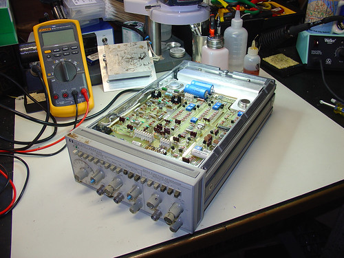
A few weeks ago, I purchased an HP 3312A 12MHz function generator for the lab. After living without a decent signal source for years, I figured that it would bepo handy to have a good general purpose function generator around. A quick visit to eBay and a few clicks later, one was on the way.
Unfortunately, when I first powered it up, the output was clamped to one supply rail and the sync output was giving me a much-too-large, out of spec voltage swing. D’oh!
The generator was sold as-is (like most test equipment on eBay), so I decided to take a crack at fixing it myself. Armed with a barely intelligible, poorly scanned-faxed-photocopied copy of the 3312A service manual that I downloaded from Agilent’s website, I loosened two captive screws and slid the top and bottom covers off the unit.
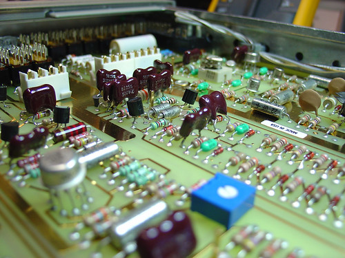
What I found inside really blew me away. What follows are some snapshots of the unit.
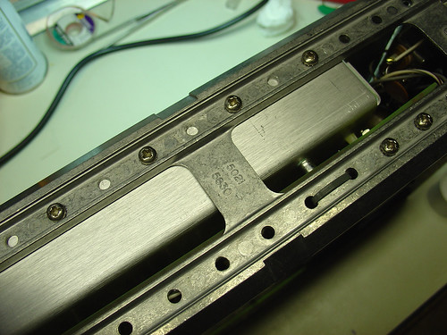
The 3312A is the most elegantly designed and well-preserved piece of electronic test equipment I that have ever owned. The circuit boards, which look brand new, use entirely two-layer through-hole construction and are laid out with generous component spacing and helpful silkscreen labels. There is no inter-board wiring to prevent quick removal of any of the PCBs; all of the wiring harnesses use straightforward connectors. Connections between the top and bottom PCBs are via clever gold plated removable posts that extend through the center panel of the instrument chassis. The chassis itself, which is cast aluminum, is light but sturdy. Every aspect of the instrument design appears to have been carefully thought out and is perfectly executed.
Here’s the 3312A on the bench, ready for some serious troubleshooting action:
The aforementioned aluminum chassis. Very nice!
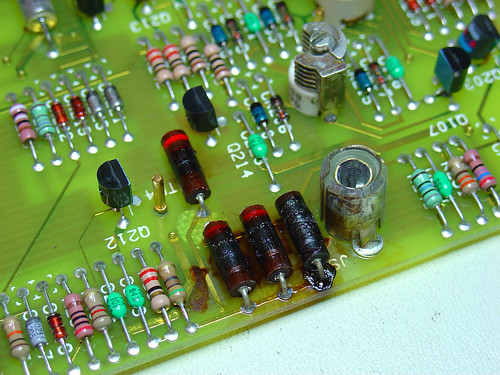
When I flipped the generator over, I immediately noticed a problem. Here are the remains of four 200 ohm, 1W carbon resistors, burnt to a crisp:
These resistors provide an internal 50 ohm termination for the sync output, and explain why the sync voltage swing was out of spec. A quick trip to Jameco for some new 200 ohm power resistors and the sync problem was fixed.
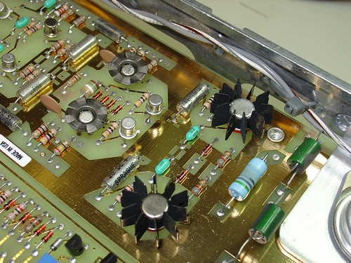
The broken main generator output took some more serious troubleshooting. One of the emitter follower transistors that drives the push-pull output driver was burning hot to the touch and a good candidate for replacement. An hour of troubleshooting with the diode test function of my Fluke 87V identified one of the push-pull transistors had failed as well. This is the device that had failed short and was clamping the output voltage to the -15V supply rail.
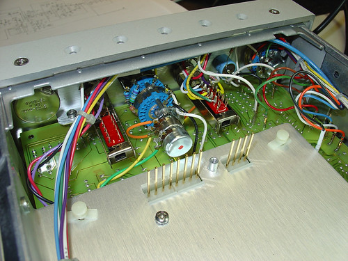
The final push-pull drivers are shown here; they are the two devices with the largest heatsinks. The emitter followers are the two metal can transistors just to the left.
I was able to find suitable replacements for the failed transistors at Jameco. Neither of the original devices were still available but I was able to find some devices that were “close enough” by examining a few datasheets and cross reference guides. With the faulty output devices replaced, the generator powered up and was good as new!
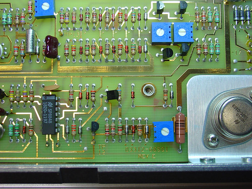
Here’s another couple shots of the main PCB. Gorgeous gold-plated traces and component layout, and some pretty components too:
Here’s a shot of the inside of the generator with the top (modulator) PCB removed so you can see the header posts that connect the top and bottom PCBs. The center aluminum plate that holds the pins in place is also removable. This allows for rework of components on the bottom (main) PCB without disassembling the entire instrument. Cool!