Immaterials: the ghost in the field from timo on Vimeo.
Check out the sidelobes on that gain pattern! More info about this project here.
via Make:

Immaterials: the ghost in the field from timo on Vimeo.
Check out the sidelobes on that gain pattern! More info about this project here.
via Make:
An HP 3312A function generator is connected to an Agilent DSO1014A oscilloscope via a length of coaxial cable. The function generator is set to generate a square wave of frequency 1MHz.
Based on the screen capture below, what is the length of the coax cable?

The first person to post a comment with:
gets some free stickers as a reward!
Hints:
The function generator claims to have an output impedance of 50Ω. Is this true? Can you make a rough estimate of what the actual output impedance is, based on the screen capture above?
Note: Random guessing is not allowed. Please show that you made some honest attempt to solve the problem, even if it is by unconventional means!
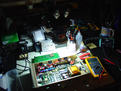
A late night in the lab spent repairing a Fluke 8840A benchtop digital multimeter.
Best viewed large.
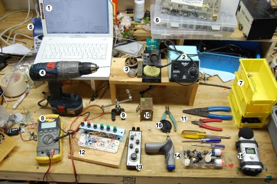
Peter Edwards of Casper Electronics shared a picture of his workbench today via Make.
With the exception of the audio recorder and circuit bending tools, pretty much every piece of equipment on that bench can be found on mine as well. I even have the same yellow bins!
There’s a great writeup on his site describing each numbered tool in the photo. If you started from scratch and bought all of the items on his list, you would have a great instant electronics workshop.

If The Art of Electronics is the bible of electronic circuit design, then the Printed Circuits Handbook is almost certainly the bible of printed circuit board (PCB) technology.
I say this because even if you disregard the volumes of useful information inside (much of which I have never seen elsewhere online or in print), this book deserves to win ‘bible’ status thanks to its 1000 pages and phonebook-quality heft!
All joking aside, this book is a great resource for anyone is serious about making good PCBs. I have worked with PCBs as a design engineer for several years now, and I learned something about printed circuit boards within minutes of opening the cover. Hours later, I was still flipping pages.
How could I walk away from a book that contains in depth discussions of topics like the difference between water soluble and no-clean flux and how to clean the leftover residue from each? Ever wondered what the myriad of surface finish options your PCB vendor offers you really mean? This book will explain the difference between HASL and ENIG, and why you shouldn’t blindly check the box that says “lead-free” without considering the consequences on your assembly process.
This is the kind of stuff they don’t teach you in school, and as a design engineer I have received only glimpses of in the industry.
Some of the highlights of this book for me are:
Be forewarned that the technical level of this book is fairly high. It is clearly targeted towards people working in the PCB industry, but most engineers and even serious hobbyists would probably get something out of it. That said, this is definitely not a book for beginners!
(And to the other design engineers out there: Want to one-up the manufacturing and reliability guys in the break room? Read this book! :-))