Tag Archives: pid

Improvements to the DIY PID-Controlled Soldering Hotplate

Improvements to PID Controlled Hotplate

Last week I posted about the DIY PID-Controlled Soldering Hotplate I designed and built to improve my surface mount soldering capabilities.

I mentioned one issue I was having with the hotplate on flickr.  Specifically, the aluminum baseplate was getting too hot for comfort (literally) when I set the hotplate to solder reflow temperatures (180-220C) for more than a few minutes.  At the time I thought it was due to radiant heat from the upper aluminum block transferring to the bottom plate.  I later discovered that the ceramic spacers I used to hold up the hotplate were much more thermally conductive than I thought and the screws I used to attach the baseplate to the spacers were burning hot before the rest of the baseplate.  It was conducted heat, not radiant, that was the primary cause of the problem!

McMaster-Carr to the rescue!

I was able to resolve the issue by reducing the diameter of the ceramic spacers from 1/2″ to 1/4″ and using all stainless hardware to attach the spacers.  Now the baseplate stays relatively cool even with the hotplate at high temperatures for long periods of time.

View the complete set on flickr.

Improvements to PID Controlled Hotplate

DIY PID Controlled Soldering Hotplate

PID Controlled Hotplate

In preparation for my Arduino-based AVR HV Programmer boards coming back, I decided to step up my home lab surface mount soldering capabilities.

Step one was to find a cheap stereo zoom microscope on ebay, with 7-32X magnification, perfect for working on surface mount devices.  One of my biggest frustrations in the past is that with a cheap magnifying ring light, I can’t actually see what I’m working on – not any more!  I’ll post some photos of the microscope when it comes.

Step two was to build a soldering hotplate.  I like using a hotplate for surface mount soldering because you can actually watch the board as the solder paste reflows, and manually add/remove/nudge components around with a set of tweezers.  This is great for engineering work where you may still be making component changes and other tweaks to the board.  Mass production is probably best left to a reflow (aka toaster) oven.

I posted a few photos of the hotplate on flickr, which ended up on Hackaday.
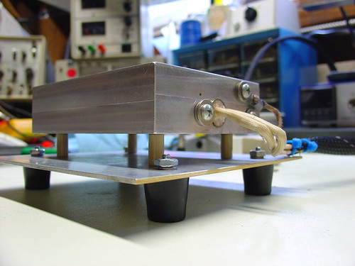
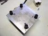
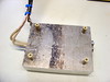
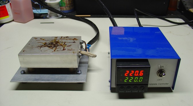
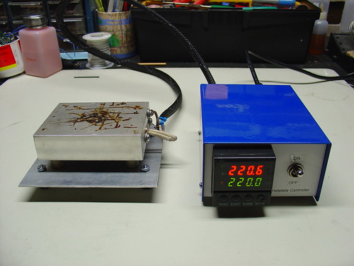
The hotplate:

PID Controlled Hotplate

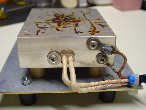
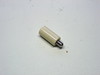
The heater is a 1/2″ 500W, 120VAC cartridge heater I bought from McMaster-Carr for about $25.  The hotplate itself is a 3x4x1″ chunk of aluminum that I machined with a carefully sized hole just below the center for the heater to slip into, as shown.  A type-K thermocouple (top right) measures the temperature and provides a signal to the controller.  Ceramic standoffs insulate the hotplate from the bottom aluminum baseplate.  For safety, there is also a ground strap, shown on the bottom right.

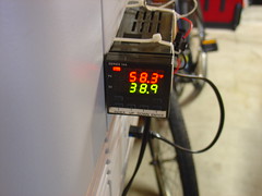
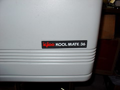
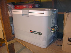
This the second PID controlled project I have done, the first was my PID Controlled Solder Paste Fridge.

The controller:

PID Controlled Hotplate

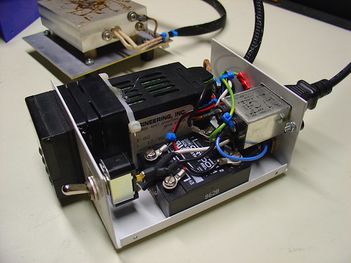
The controller box contains an Omega CN77000 series PID controller and an IR/Crydom 240V 40A (overkill!) D2440 Solid State Relay (SSR), along with a power switch, fuse, and power connector.  The PID controller and solid state relay were both found at a now-defunct Silicon Valley surplus store for a few bucks each.  A 3′ umbilical cable connects the controller to the hotplate.

60/40 leaded solder reflows at about 185C, and lead-free solder is around 200-230C depending on the alloy.  (Wikipedia has a good list of reflow temperatures.)  The hotplate can easily reach these within a minute or two from room temperature and could get much hotter if necessary.

It can also be used to cure epoxy and perform any other tasks that require a precisely controlled heater – this could be the world’s most overengineered coffee warmer, if not for the dangers of lead poisioning.

Update: I just posted some more information about the microscope.

PID Controlled Solder Paste Fridge

PID Controller closeup

I recently decided I needed to upgrade my garage electronics bench to include capability to work on surface mount components.  I ordered a hot air reflow station and some no-clean solder paste from SRA.

Solder paste is a little tricky to handle, because most solder paste needs to be refrigerated at 32-50°F to maintain it’s shelf life.  Stored at room temp, it tends to get tacky and dry out within a few weeks.  Solder paste is also toxic (it contains lead among other things) so it’s not something you want to put in the fridge with your meatloaf.

I had an old beer cooler sitting in the garage that Kylie picked up on the street a while back.  It uses a Peltier thermoelectric cooler to cool the inside and can achieve sub-freezing temperatures.

PID Controlled Solder Paste Fridge

Since I didn’t want to leave the cooler on constantly, and below freezing is actually too cold for solder paste, I decided to add a PID controller to the cooler to create a solder paste fridge for the garage.  To do this, I needed the following items:

  • Love Controls 16A PID Controller found at a surplus store.  This one happens to run on 12V and also has a 15V output which made things simple, but other configurations are possible and almost any PID controller should work provided it supports “direct” mode (for cooling instead of heating) and has a relay or switched voltage output.
  • K-type thermocouple to measure the inside temperature of the cooler
  • power MOSFET capable of switching 12V @ at least 5A, lower on-resistance is better.
  • 1k bleed resistor to ensure the MOSFET turns off when it’s supposed to
  • a small heatsink for the MOSFET (may be unnecessary, mine doesn’t even get warm)

Since the PID controller happens to run on 12V I was able to use the existing 12V power supply for the cooler to power everything.  I configured it so that if the desired temperature is below the current temperature, the PID controller turns on the MOSFET which supplies power to the Peltier cooler and it’s associated fans.

The only hangup I had was that at first I didn’t place the 1k resistor across the output of the controller, and the cooler would stay on constantly.  It turns out that because MOSFETs have almost no gate current, once the PID controller turned off it’s 15V output, the gate of the FET would continue to float high.  The bleed resistor to ground ensures that this can’t happen, and the FET turns off properly.

Here’s a picture of the finished solder paste fridge complete with PID controller (click for a larger version).

Finished PID Controlled Solder Paste Fridge

You can check out a bunch more photos of the cooler on flickr.  It should be possible to perform this modification on a more conventional mini-refrigerator as well for better control over the temperature, provided it uses a Peltier cooler, or maybe you could even build the whole thing from scratch using a Peltier cooler off ebay.