Hal created a neat project by taking parts of my Wifi Radio project and repurposing them to do something completely different. His Standalone Weather Station changes the color of an LED based on the weather forecast for tomorrow. If temperatures are trending warmer, the color changes towards red. Colder – blue.
His project is very well documented and includes code for both the ATmega168-based circuit that drives the LED using PWM and the shell script on the router that communicates with Weather Underground to get the forecast.
This is the eighth part of an ongoing series about building a low cost, open source streaming internet radio based on the ASUS WL-520gU Wireless Router. If you haven’t already, check out the previous parts (see the links at the end of this article) for some background about the project.
In part seven, we added an LCD status display for the radio that shows the stream name as well as the artist and title of the current track. In this part, we’ll add a tuning knob that lets us change stations without using a computer.
It turns out that this is mostly a software exercise, made simple by taking advantage of the analog to digital converter function of the Atmel ATmega168 AVR that is controlling the LCD display. The addition of the tuner control turns the display circuit into a very simple user interface. Turn the knob and the station changes. The position of the knob determines what station the radio is “tuned” to, and when combined with a calibrated scale it will make it easy to change to any one of the several streaming radio stations stored as presets (favorites?) in the router.
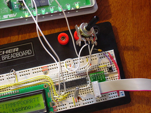
To give you an idea of how this works, here is a demo of the tuner control changing between ten preset stations I have set on the router. The tuner control is in the upper right hand corner of the breadboard. As I adjust the control, the music changes and LCD display updates to show the name of each new station.
Is that cool or what?
If you are interested in adding this functionality to the radio, keep reading and I’ll show you how.
Changes to the hardware:
You will need:
The completed AVR-based LCD display from part seven
A 1k-10k trimmer or potentiometer, linear taper
Some hookup wire
Schematic:
Here is an updated schematic of the AVR circuit showing the potentiometer connected to ADC4 (pin 27).
click to enlarge
Firmware:
The AVR firmware has been significantly expanded, slightly reworked and cleaned up in some areas.
The most important changes are:
The addition of a serial transmit function so the AVR can talk to the router (based on the uart_putchar function)
New code supporting the analog to digital converter (ADC) which reads the value of a potentiometer connected to ADC4.
A new Timer1 overflow interrupt has been added, which occurs roughly every 0.5 seconds. The interrupt service routine (ISR) checks the position of the tuner control, and if it has changed, sends the value to the router. The ISR is towards the top of the file, see the SIGNAL (TIMER1_OVF_vect) section.
The ADC range of the ATmega is 0 – 1024 for an input voltage from 0 to 5V. The AVR sends serial data in the format “Tuner: Value” back to the router when the tuner position changes by more than ADC_SENS counts (default is 5). The AVR waits for an “AVR Start!” command from the router before sending any data, this avoids filling up the serial receive buffer on the router before it’s ready to start processing data. An important consequence of this is that the AVR must be reset before running the control script on the router.
You can download the source code and compiled .hex file here. Flash it to the AVR using any compatible ISP programmer and you should be good to go. The source is commented fairly well so if you’re interested in learning how the interface works, take a look. You will need a copy of the ATmega168 datasheet to understand the register names and other architecture-specific parts of the code. Feel free to post in the comments with any questions.
Modifying the circuit:
This part is pretty simple – just wire the potentiometer as shown in the schematic. Most potentiometers have three terminals. The left terminal goes to ground, the right one to +5V, and the middle terminal to ADC4 on the AVR (pin 27).
Tweaks to the OpenWrt configuration:
To make bidirectional communication with the AVR work, we have to change a couple config files on the router and disable some services that would otherwise get in the way.
/etc/config/network
The first change is to modify the /etc/config/network file so that we can always telnet or ssh into the router on a LAN port using the IP 192.168.1.1. The ability to access the router via ethernet is helpful in case we screw something up and lose the wireless connection or the router loses it’s IP address, etc.
Modify the LAN section of /etc/config/network to look like this (changes in bold):
#### LAN configuration
config interface lan
#option type     bridge
option ifname    "eth0.0"
option proto    static
option ipaddr    192.168.1.1
option netmask    255.255.255.0
Save changes, restart the router, and connect an ethernet crossover cable (straight cable might work on some computers) to the router. Configure your desktop/laptop computer with a static IP, like 192.168.1.185. Try to open a telnet connection (or ssh if you have set a password on the router) and see if you can log in. If not, don’t continue with the next steps until you can get this working.
/etc/inittab
We previously used the router’s serial port to get a login shell. Now that we’re trying to receive data from the AVR on the same serial port, we need to disable the login shell or it will capture the data before we can get to it.
Edit /etc/inittab to look like this (changes in bold):
::sysinit:/etc/init.d/rcS S boot
::shutdown:/etc/init.d/rcS K stop
#tts/0::askfirst:/bin/ash --login
#ttyS0::askfirst:/bin/ash --login
tty1::askfirst:/bin/ash --login
/etc/sysctl.conf
Sysrq is a fascinating and very low level debugging feature of the Linux kernel. It can be used to perform troubleshooting operations and reboot the system. Usually it is invoked with a magic key combination on a desktop computer, but in this case I found that it is easy to accidentally trip over the serial port when using an AVR. (The “break” RS-232 code triggers Sysrq, this probably has something to do with it.)
Fortunately, it’s easy to disable by editing the /etc/sysctl.conf file and adding these lines:
# Disables the magic SysRq key
kernel.sysrq = 0
Reboot the router to apply the changes. Now we can get on with the good stuff!
Shell scripting magic:
The real action happens on the router, where a shell script waits for input from the router and changes the station accordingly.
This script is called interface.sh and can be downloaded to the router using wget as shown:
Once both scripts are downloaded, executable and located in /root you can launch interface.sh as follows:
root@OpenWrt:~# ./interface.sh
volume: 60%   repeat: on    random: off
volume: 60%   repeat: on    random: off
adding: http://relay3.slayradio.org:8000/
adding: http://scfire-dtc-aa01.stream.aol.com:80/stream/1046
adding: http://208.101.28.234:8004
… more stations here …
Tuner Position:  0
New station...
http://relay3.slayradio.org:8000/
[playing] #1/10   0:00/0:00 (100%)
volume: 60%   repeat: on    random: off
The interface script adds ten presets to the router, shows the playlist, and then waits for valid tuner data from the AVR. Once it receives a “Tuner: value” line (which should occur shortly after the AVR receives a go signal from the script), the script prints the received tuner positon and changes to the requested station. It will then wait for new tuner data from the AVR and change the station when necessary.
As you can see in the video, this works very well. Over a fast Wi-Fi connection, the time to change stations is almost instantaneous – very satisfying!
That’s it for part eight. In part nine, I’ll add some finishing touches to the router configuration and start talking about enclosures. Stay tuned!
Update: There is a new Wifi Radio Discussion Forum, hop over there to ask questions about the project or see what other people are working on! (4/12/09)
In response to the continued demand for a PCB version of my Arduino-based AVR High Voltage Programmer, I just released a first cut to BatchPCB and should have a prototype within 3-4 weeks.
This design is an improvement upon the original HV programmer shield in the following areas:
Onboard 12V boost converter eliminates the need for an external 12V power supply
Support for two of the most common families of AVR microcontrollers, the ATmega48/88/168 and ATtiny2313
Separate Ready and Burn indicators
Protection resistors on every single data, control, and supply line to the target AVR, meaning that your Arduino and AVR should survive any mishaps during programming, including inserting the AVR backwards or off by 1 pin.
I hope to have kits for sale in early February. Sorry for the delay in getting these made, but I wanted to make the best possible shield I could!
Let’s say you are designing a printed circuit board in Eagle, and you need to place a component that you’ve never used before. In Eagle, before you can use a new component, you need a land pattern, a schematic symbol, and a mapping between them to fully define the part. Often, you can search through Eagle’s included libraries and find what you need (or something close enough). But what if that fails?
The symbol and pin definitions are usually pretty easy – just copy the datasheet. The hard part is the land pattern: the collection of copper traces, soldermask openings, silkscreen, and other features that define the part on the PCB.
To come up with a land pattern, you usually have a few options:
Someone else may have done you a big favor by creating a part definition and uploading it to the Eagle library directory. Caveat: Use it at your own risk. Surface mount parts tend to be particularly hard to use right out of the box – often someone else’s land pattern won’t even pass your DRC. Whose process were they using, anyway??
Look through the datasheet for the part to try and find a recommended land pattern. (Good luck! Increasingly these are not included, but may be somewhere else on the manufacturer’s website. Google is your friend!)
Take a guess based on the geometry of the part, assuming you have a mechanical drawing or a physical sample somewhere.
Skip 1-3 and use an IPC-7351 land pattern generator.
IPC-7351 is a standard for printed circuit board land pattern designs. The standard attempts to, well, standardize land patterns to try to discourage every PCB designer from having his or her own custom library of land patterns. IPC takes known good land patterns and combines them with accepted manufacturing tolerances to produce a land pattern that will work for most people most of the time. Increasingly you will see references to IPC-7351 in datasheets instead of a land pattern drawing, so access to the standard is becoming more important over time.
Fortunately, PCB Matrix has a free IPC-7351 Land Pattern Calculator (direct download link here) that you can use to generate land patterns based on the standard. You don’t need to own a copy of the standard to benefit from it.
The calculator is somewhat tricky to use but if you click the right buttons you can get something like what is shown below (click to enlarge).
PCB Matrix IPC-7351 Land Pattern Calculator Screenshot
X and Y are the dimensions of the recommended pads for an 8-lead Thin SOT-23, which happens to be the package for the LT3464.
With this information, you can return to Eagle and create a land pattern for your device. PCB Matrix will also sell you premade Eagle libraries, but from their site it was not clear how much they cost. Based on their other products, my guess is several hundred dollars and a yearly maintenance contract – I’ll draw my own, thanks.
Unfortunately, the calculator is Windows only, so Mac guys like me need to use VMware Fusion or similar to use it. Can someone create a web version, please?
Programming & Customizing PICmicro Microcontrollers, by Myke Predko, is probably the best book out there for someone who is starting out with the PIC series of microcontrollers from Microchip. I used Myke’s book as both a tutorial and reference when I created my PIC RGB Video Display. Since then, I have referred back to this book countless times even when working with other microcontrollers, like Atmel’s AVR family, because it contains so much useful architecture-independent technical information. I have referred to this book for information about topics including LCD interfacing, debouncing switches, RS-232 serial interfaces, and multiplexed LED drivers. As a technical reference it easily surpasses the majority of AVR books that are out there.
The book is starting to show it’s age by not including some of the latest PIC micros in the examples (like the PIC16F628), but the code is easily ported to newer/faster/better microcontrollers, a good learning excercise in itself.