This is the seventh part of an ongoing series about building a low cost, open source streaming internet radio. If you haven’t already, check out the previous parts (see the links at the end of this article) for some background about the project.
In part six, we used OpenWrt’s UNIX-style shell commands to interface with mpd, the music player daemon, and redirect song and stream information to our ASUS WL-520gU wireless router’s serial port. In this part, we’ll use a Sparkfun 16×2 LCD display and a handful of other components to build an LCD status display for the radio.
The Atmel AVR Microcontroller:
After much thought, I decided to use an Atmel ATmega168 AVR microcontroller to drive the display. I realize that this raises the technical level of this project significantly, but I have been wanting to feature an AVR project on the site and this is a great opportunity. The truth is that an Arduino would work just as well and it shouldn’t be too difficult to port this program to an Arduino sketch. (The Arduino is built with the same ATmega168 microcontroller, after all.) If anyone does this, let me know and I’ll post a link to your version of the display.
If you’re an AVR veteran, you can skip over this part and straight to the bill of materials below.
If you are new to the AVR, don’t be intimidated. There are a number of tutorials online to help you learn how to use this inexpensive and powerful microcontroller. I recommend starting with this one or maybe this one, but see my note about AVR MacPack below if you’re using a Mac. If you’ve never programmed in C before, you’ll have an additional hurdle to get over, although for this project you won’t need any actual knowledge of programming or C to burn the code to the AVR and get things working.
You will need to install some software to work with the AVR, I recommend:
- AVR MacPack for OS X (the Adafruit tutorial recommends OSX-AVR, use this instead)
- WinAVR for Windows
I recommend following a tutorial or two and getting a simple blinking LED example working on your AVR before building the LCD display. That way you can be sure your programmer, development environment, breadboard, etc are working first.
Building the display:
Bill of Materials:
You will need:
- one A-B USB cable (the kind with one flat and one square end)
- an AVR programmer, such as the Adafruit USBTinyISP
- an Atmel ATmega168 AVR microcontroller
- a working AVR development suite or at least a way to get a .hex file onto an AVR (see above)
- an LCD display like this fancy LED backlit Sparkfun 16×2 Character STN
- a solderless breadboard, like this one (comes with precut wires!)
or this one.
- a 4-pin female 0.1″ header, this breakaway header is handy.
- two 22pF ceramic capacitors, rated >6V (mine are 25V)
- a 0.1uF capacitor, rated >6V
- a 10 Ohm resistor
- for contrast adjustment, a small 1k or 10k potentiometer
- a few feet of 20 to 24 gauge solid hookup wire
also nice, but not required:
- a Sparkfun ISP breakout board to simplify connecting the programmer to the breadboard
- a normally-open pushbutton switch to reset the circuit
Schematic:
Here is the schematic of the LCD display (click to enlarge):

Firmware:
You can download the source code and compiled .hex file here.
Special thanks to Peter Fleury for his excellent LCD library, which saved me from reinventing the wheel! He also has another page about interfacing LCD displays to an AVR.
Assembling the circuit:
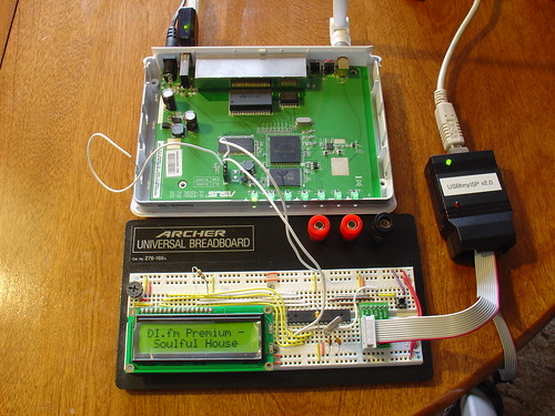
Assembling the circuit on the breadboard is pretty straightforward. Here’s a photo showing all components of the setup. The router is shown above with the serial port wired to the breadboard (the RX line is floating as we’re not using it yet). The USB AVR programmer is on the right, where it is also functioning as a 5V power supply for the circuit. Make sure the 2-pin jumper on the USBTinyISP is installed, this enables the +5V supply. The LCD is shown displaying the current stream name (DI.fm).
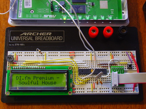
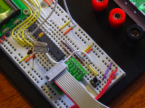
Here is a closeup of the components installed on the breadboard to show how I did things, feel free to experiment with the placement of components. As long as you follow the schematic the circuit should still work.
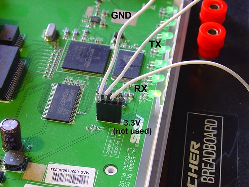
Here is a closeup of the serial port connection to the router, including the 4-pin female 0.1″ header. I soldered wires to the pins of the female header (not the pins on the board).
Here is a closeup of the AVR, crystal, and the Sparkfun ISP breakout board showing the pinout:
Flashing the AVR:
Once the circuit is assembled on the breadboard, we need to flash the AVR microcontroller with the main.hex file included with the firmware above.
If you’re using AVR MacPack and OS X, this should be easy (since that’s what I’m using). PC guys will need to figure this out for themselves but hopefully the process is similar (please let me know if the Makefile works).
Connect the USBTinyISP to your computer with the USB cable and to the breadboard with the ISP cable. The green light on the programmer should be on, indicating it is ready, and the backlight of the LCD should be lit, indicating that the breadboard is getting power.
Open a terminal window and create a new directory, I used ~/temp. Unzip the firmware into a directory somewhere, and execute ‘make flash’, as shown:
macbook:temp jkeyzer$ unzip ./AVR_wifiradio_display.zip
Archive:  ./AVR_wifiradio_display.zip
  inflating: lcd.c
  inflating: lcd.h
  inflating: main.c
  inflating: main.hex
  inflating: Makefile
macbook:temp jkeyzer$ make flash
avr-gcc -Wall -Os -DF_CPU=16000000 -mmcu=atmega168  -c main.c -o main.o
a few warnings later …
avr-gcc -Wall -Os -DF_CPU=16000000 -mmcu=atmega168  -c lcd.c -o lcd.o
avr-gcc -Wall -Os -DF_CPU=16000000 -mmcu=atmega168  -o main.elf main.o lcd.o
rm -f main.hex
avr-objcopy -j .text -j .data -O ihex main.elf main.hex
avrdude -c usbtiny -p atmega168 -U flash:w:main.hex:i
avrdude: AVR device initialized and ready to accept instructionsReading | ################################################## | 100% 0.01savrdude: Device signature = 0x1e9406 avrdude: NOTE: FLASH memory has been specified, an erase cycle will be performed To disable this feature, specify the -D option. avrdude: erasing chip avrdude: reading input file "main.hex" avrdude: writing flash (1326 bytes):Writing | ################################################## | 100% 3.32savrdude: 1326 bytes of flash written avrdude: verifying flash memory against main.hex: avrdude: load data flash data from input file main.hex: avrdude: input file main.hex contains 1326 bytes avrdude: reading on-chip flash data:Reading | ################################################## | 100% 0.68savrdude: verifying ... avrdude: 1326 bytes of flash verifiedavrdude: safemode: Fuses OKavrdude done. Thank you.
If everything went well, the LCD display firmware is now loaded into the ATmega168 and the circuit is ready to go. If not, double check your connections and take a look at the help! page for the USBTinyISP.
Testing the display:
Telnet or ssh into the router. Start mpd and connect to a stream using mpc (we covered this in part five).
Once the stream starts playing, execute the display.sh script we created in part six. Within a few seconds, if everything is working, you should see the stream name on the display, followed by the artist and name of the current song. Congratulations!
Here is a video of the LCD display in action, including the horizontal scrolling feature to show information that is too wide to fit within the visible area of the display:
That’s it for part seven! In part eight, we’ll start working on the input side of the user interface.
Like what you’re seeing? Have suggestions about what could be improved? Leave a comment or contact me directly.
Update: Part eight, in which I add a tuning control to the radio, is now available.
Update 2: There is a new Wifi Radio Discussion Forum, hop over there to ask questions about the project or see what other people are working on! (4/12/09)