Wow, 2010 came a lot quicker than I expected! With one day to spare, here’s a brief look back at some of the highlights of 2009 here at mightyohm.com.
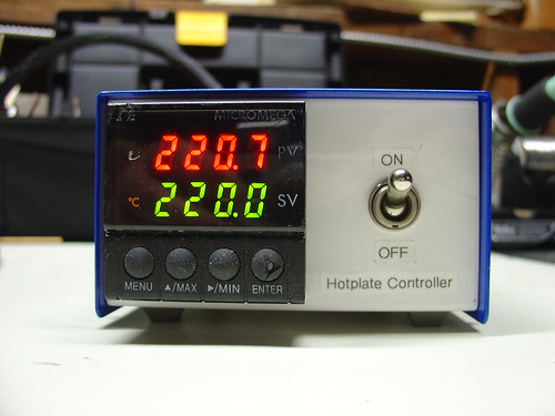
DIY PID-Controlled Soldering Hotplate:
I needed a hotplate for surface mount soldering, so I built one from scratch using a milled block of aluminum, a 500W cartridge heater, and a surplus PID controller. Some of my favorite DIY projects have been building my own tools, and this one is a great example.
The AVR HV Rescue Shield:
This year saw the release of my first electronics kit, the AVR HV Rescue Shield. Designed in response to my own experience accidentally setting the RSTDISBL fuse on an AVR microcontroller, the AVR HV Rescue Shield has helped many microcontroller enthusiasts around the world rescue their otherwise crippled, stuck, or deaf AVR’s.
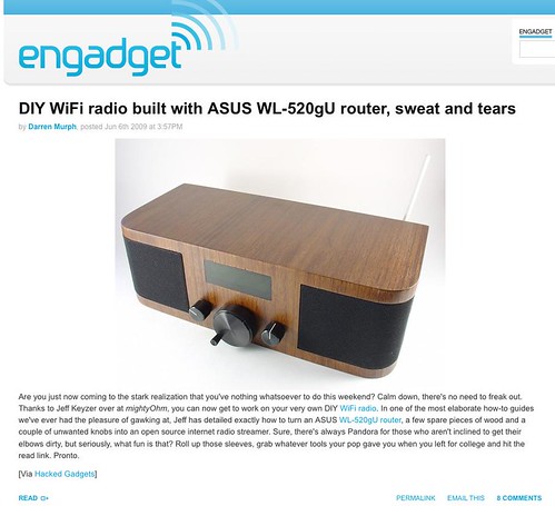
In April I flew out to Cleveland and gave a talk about Hacking the Asus WL-520gU Wireless Router at Notacon 6. The con was a huge amount of fun but reminded me just how much work it is to give a talk. I met lots of cool people there, including George Sanger and Jeri Ellsworth, aka The Fatman and Circuit Girl.
By the way, the submission deadline for talks at Notacon 7 closes on January 31st!
DIY TiVo IR Blaster:
My DIY TiVo IR Blaster was a simple hack constructed in an hour entirely out of parts I already had in the lab. The best part is that eight months later, it’s still working flawlessly. Like any good hack, this one is cheap, simple, and just works.
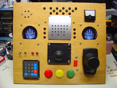
Harrison’s Box:
This project, codenamed “Harrison’s Box“, was a collaboration with my wife Kylie and my father-in-law Bill to build an “electronic box” to give to my nephew Harrison’s on his first birthday. We added as many switches, knobs, and lights as we could. Harrison loved it!
Those are some of the highlights of 2009. I hope to bring more cool projects, hacks, and kits to you in 2010!
Lastly, Happy New Year and a sincere thanks to everyone who has been reading the blog, leaving comments, buying kits, or supporting the site in some way over the past year!
Welcome to Part 3 of the Diamond Chop Saw build. In this installment I’m going to focus on the construction of the mechanical aspects of the saw structure, motor attachment, vacuum chuck, and splash guard. This is a picture-heavy entry…
After thinking for a while about how to build the saw, I decided that it would be best to have the blade move only in the vertical axis, and the workpiece move horizontally in two axes. This led to the overall machine design which consists of a vertical column with pivoting cutting head assembly, and a workpiece holder that has two axes of horizontal motion.
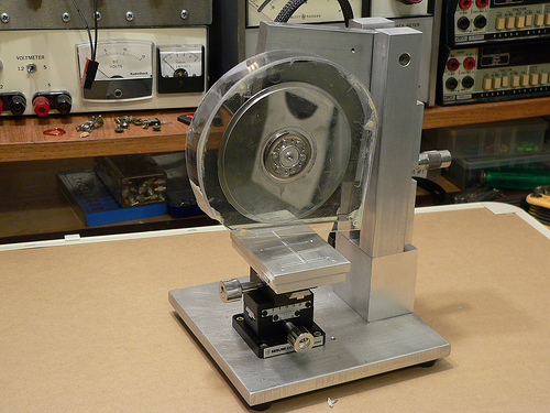
Completed Dicing Saw
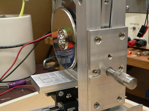
I wanted to ensure the motor and blade had a rigid, heavy mounting structure to reduce effects of vibration and flex on cutting performance. I decided to mount the motor using the original mounting flange from the hard drive enclosure since it was nicely machined to match the motor flange. I used a hacksaw to cut out the shape roughly to size, then straightened up the edges and machined a mounting recess on my milling machine. The L-shaped piece of aluminum is 1/2 inch thick which gives lots of weight and provides sufficient thickness for mounting the bearing while preventing motion orthogonal to the bearing axis.
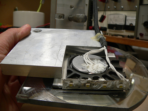
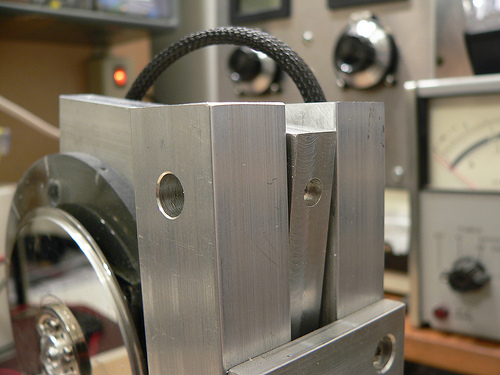
Cutting Head Assembly
Another view of the cutting head assembly. In the upper left hand corner is the pivot bearing. The bearing is held in place with a set screw that goes through the L-shaped aluminum piece. Along the bottom edge of the black hard drive enclosure portion I attached a strip of white LEDs to help light the work area. RTV Siliconeis used to seal the electrical contacts from water that migt not be caught by the splash shield. At the lower left hand corner of the aluminum plate is a rounded off screw. The cutting depth adjustment micrometer pushes against this rounded off screw. Pushing against the aluminum would be less accurate (aluminum would become unevenly worn).
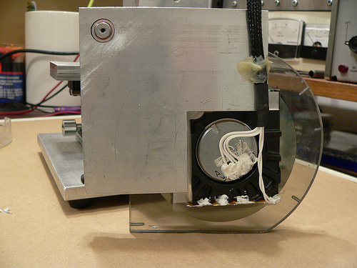
Cutting head assembly (rear view)
At the top of the column on either side is a hole for the screws that hold the pivot bearing (also from a hard drive) in place. Luckily the one I used has 4-40 threaded holes on either side. A screw on each column holds the bearing in place, and then the rest of the column assembly and adjustment plate are attached resulting in a good alignment of the column to the bearing.
Pivot bearing/column mounting detail
Controlling the depth of the cut is critical, as my cuts will be as small as 5 thousandths of an inch deep! I mounted a micrometer head to a plate on the back of the column which controls the height of the cutting head assembly.
Rear view of the column and depth adjustment control
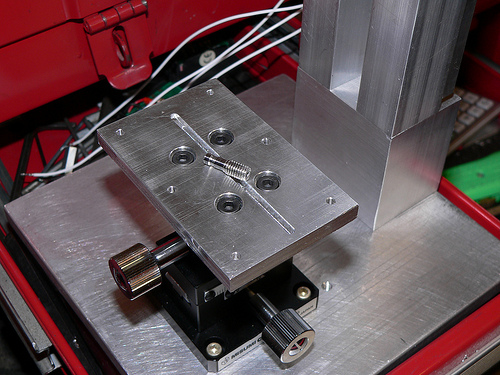
Now for a little detail on the vacuum chuck… The chuck is made from two 1/4 inch plates of aluminum. The top surface has a shallow set of trenches cut to distribute the suction across the bottom surface of the glass plate used for holding parts. The lower plate has a deep trench cut in it to distribute the suction to the three small holes drilled on the top plate. The whole thing is held together with screws and sealed with silicone. I made a set of hose barbs (one is pictured below) so that I can use 1/8 inch vinyl tubing to connect to my vacuum pump. The barbs were made by turning down 10-32 stainless steel screws on my lathe.
Lower half of vacuum chuck with custom-made hose barb
The last major component of the saw is the splash guard. This actually took a fair amount of effort to make, as I broke pieces more than once and had to start over. Essentially it is a two-piece design with a thick piece screwed to the cutting head assembly, and a thinner piece which screws onto the first. I used a heat gun to soften the plastic and carefully mold it to the shape of the face plates. I then glued the curved section and the outer face plate together using epoxy and while not very pretty, it holds together well.
Splash guard on the saw
That pretty much sums up the mechanical aspects of the saw construction. Next week I’ll post the 4th and final installment which will include alignment and attachment of the blade, and actual use of the saw!
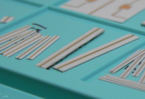
10, 20, and 5 mil thick alumina substrates with 50 ohm transmission lines
In part 1 I gave an overview of what this project is all about. In this part I will describe the basics of the machine and some of the reasons I made the design choices I did. To start with, I wanted to do this on as small a budget as possible. The main project for which this machine serves ends up being a real money pit, so I have to budget accordingly. Hence the use of hard drive parts and scrap metal. Total spent so far is about $60.
When I first thought about how to cut these little pieces of ceramic, it seemed that there were a few elements that would be tricky on a budget. First thing I did was try and figure out how commercial dicing saws work. Certainly Intel and others have figured out a good way to slice ’em and dice ’em a long time ago… And they did.
Tricky thing #1: Holding the substrate while it is being cut.
After a wafer full of chips is finished being made, it is mounted onto a wide stretchy tape, creatively named “dicing tape.” The tape is pulled over a frame and then the wafer placed on top. Next the taped wafer goes into the dicing machine where it is cut by an insanely fast spinning diamond encrusted blade of blingy wafer death.
To keep the wafer from heating up (chips generally don’t like heat) water is sprayed at the cutting surface. This also helps to wash away crud generated by cutting and to prolong blade life. Once the wafer has been diced into individual chips, the tape is exposed to UV light or heat. The adhesive on the tape is made to become less sticky when exposed, and at this point the chips can be easily removed with tweezers, or an automated pick-and-place machine.
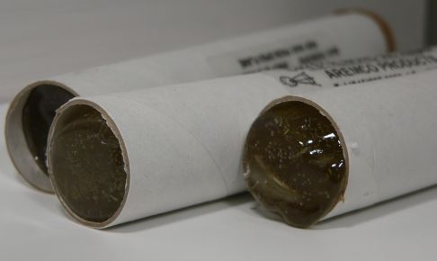
My first thought was to try and get some of this tape and use it in the same manner, but for smaller pieces. Then someone at work told me about something far more cool, with a far better name, something called Crystalbond! Crystalbond is essentially a mounting adhesive designed for exactly what I want to do. You simply heat it up, it becomes liquid, place the part in the puddle, and then do nothing until it cools off and then solidly holds your part. I managed to find 5 lifetime’s supply on eBay for dirt cheap, but several other places sell it. Anyway after the parts are cut you wash it away with acetone and you are left with clean diced parts.
Tubes of Crystalbond mounting adhesive
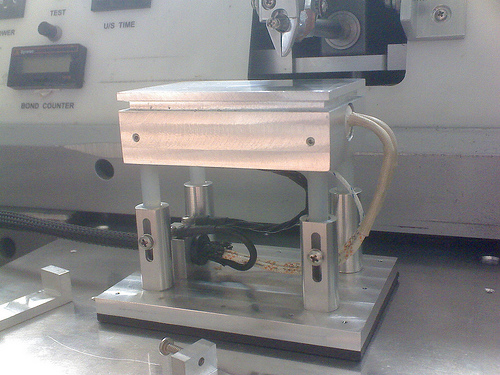
Okay, so the part can be held, but I didn’t want to have to glue a part to my machine every time I wanted to cut something. So instead of gluing the part to the machine I decided to glue the part to small pieces of glass which are a convenient carrier and can be used with my hotplatethat I built for my wire bonder.
Hotplate for thermosonic wedge bonding
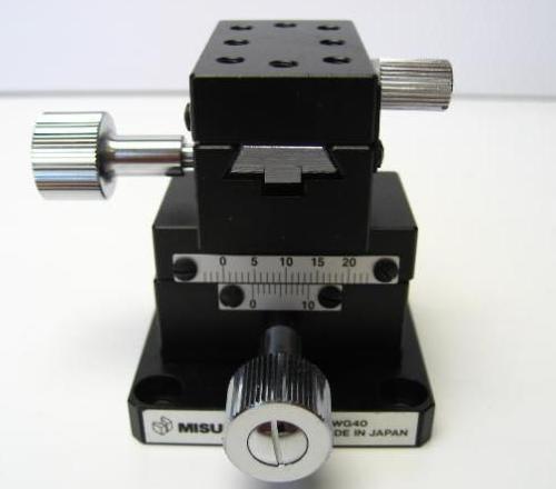
So now I’ve got a piece of easy to handle glass, with one or more substrates to dice which has to be mounted to the machine. I could use tape, a temporary adhesive, or clamps, but why? I just put together a digitally controlled vacuum pump for some composites work, so why not make a vacuum chuck? And even better, I mounted it to a precision X-Y dovetail slide that I purchased on eBay for cheap. Now I can easily position the glass, reposition if necessary, and make measured cuts my moving the X-Y stage and measuring at the same time with a runout gauge. This allows me to make cuts that are accurate to 0.001 inches.
X-Y positioner I bought off eBay
A note here regarding XY stages… I chose specifically a dovetail style positioner because unlike the more common linear bearing style slides, a dovetail slide has static loading. The benefit is that there is a much greater resistance to vibration and since I am grinding, I want as solid a mount as possible.
This is really a compound Tricky Thing, a combination of finding the blade, holding it, and spinning it. First a little background on dicing saws and blades…
Wafer dicing used to be done (and still is, especially in research situations) with a diamond scribe, basically a pencil with a diamond at the end. A small scratch is made along the crystal plane of the wafer and then carefully bent until a long, very straight crack is made through the wafer.
The same can be done with alumina substrates, although since it is not a mono-crystalline structure, the crack won’t be as straight or as predictable. Scribe dicing is a relatively labor intensive task and chip manufacturers HATE labor, but even more than that they REALLY HATE any time that an actual person touches a wafer.
Wafer dicing today is usually done with a very thin diamond abrasive blade that grinds away the metal or semiconductor until a cut is made. It is nearly identical to the way you might cut tiles when doing a counter top in your kitchen but on a much smaller scale. When cutting tile, if the blade wobbles a bit or is not centered perfectly, you are not likely to notice. With the alumina substrates I’m working with, the pieces are 20-40 times thinner. This implies that any vibration, wobble, or eccentricity errors can cause problems.
Commercial wafer dicing machines use high speed motors that are carefully balanced and rather than using ball bearings, employ costly air bearings. These are essentially out of reach for hobbyists and really not necessary. What is necessary though is a way to hold and spin the blade accurately. Dicing blades are thin, and the thickest ones I could find on eBay were 300 um wide. At 4.6 inches in diameter, a a very large inner diameter, they are also hard to accurately mount on a typical spindle like that found on a Dremel tool.
Diagram depicting blade mounting: Part A shows the original platter and spacer configuration, Part B shows the modifications I made, Part C shows the blade mounted.
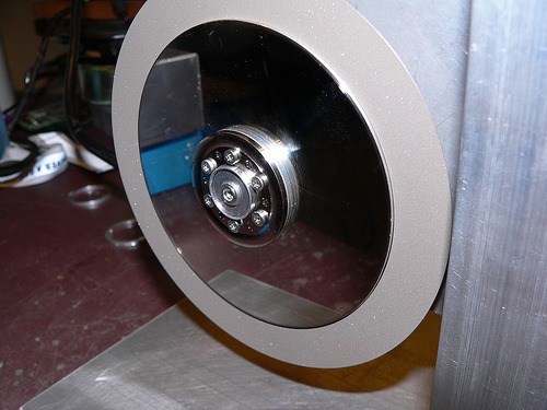
All of these issues led me to use a hard drive motor and platters to spin and hold the blade. Hard drives have very long service lives and need bearings of the highest precision. The mounting of the platters is also done in a precise way, as any imbalance would shorten the bearing lifetime and result in undesirable operation.
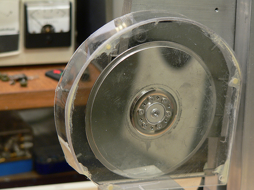
To make a long story short, I removed (and reused) the spacer ring between the two platters of a hard drive, and reduced the radius of one platter to 3.5″, the inner diameter of the blade. You can see in the picture that the two platters are stacked and there’s a nice surface for gluing the blade down. Machining the platter down was not easy with my tiny lathe, and it ended up being out of round by perhaps 10 mils. It works to roughly locate the blade, but I will need to tack the blade down, measure, adjust, and finally glue into place. 10 mils out of round is really bad because the thickest substrate I’m working with is 10 mils thick. That means that one part of the blade would never actually do any cutting!
Blade test fitted to the saw.
Tricky Thing #3: Driving the motor
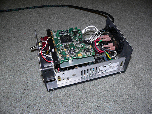
This seemed to be slightly daunting at first. Hard disk motors are typically some kind of brushless motor and require special circuitry to run. I imagined that I would have to build a circuit, or use a motor speed control from a radio controlled plane, etc. It turns out though that the main circuit board in the hard drive I’m using is dumb enough that even though it has had the equivalent of a frontal lobotomy, it just keeps doing it’s job. A couple other hard drives I tore apart did not do this.
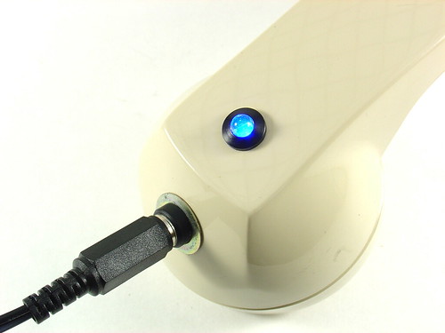
Motor Control Box
The box in the picture above shows the hard drive main circuit board and below that, a 12v/5v switching power supply. It’s pretty basic and at the flip of the switch on the front panel, the DC supply is connected to the motor driver and voila, the motor spins up.
Schematic Diagram for the Motor Control Box
Well, that’s about it for this part. In the next part I will discuss the mechanical structure of the saw, fabrication of a few parts, and in the final installment, the use of this machine.