Tag Archives: DIY

Improvements to the DIY PID-Controlled Soldering Hotplate

Improvements to PID Controlled Hotplate

Last week I posted about the DIY PID-Controlled Soldering Hotplate I designed and built to improve my surface mount soldering capabilities.

I mentioned one issue I was having with the hotplate on flickr.  Specifically, the aluminum baseplate was getting too hot for comfort (literally) when I set the hotplate to solder reflow temperatures (180-220C) for more than a few minutes.  At the time I thought it was due to radiant heat from the upper aluminum block transferring to the bottom plate.  I later discovered that the ceramic spacers I used to hold up the hotplate were much more thermally conductive than I thought and the screws I used to attach the baseplate to the spacers were burning hot before the rest of the baseplate.  It was conducted heat, not radiant, that was the primary cause of the problem!

McMaster-Carr to the rescue!

I was able to resolve the issue by reducing the diameter of the ceramic spacers from 1/2″ to 1/4″ and using all stainless hardware to attach the spacers.  Now the baseplate stays relatively cool even with the hotplate at high temperatures for long periods of time.

View the complete set on flickr.

Improvements to PID Controlled Hotplate

DIY PID Controlled Soldering Hotplate

PID Controlled Hotplate

In preparation for my Arduino-based AVR HV Programmer boards coming back, I decided to step up my home lab surface mount soldering capabilities.

Step one was to find a cheap stereo zoom microscope on ebay, with 7-32X magnification, perfect for working on surface mount devices.  One of my biggest frustrations in the past is that with a cheap magnifying ring light, I can’t actually see what I’m working on – not any more!  I’ll post some photos of the microscope when it comes.

Step two was to build a soldering hotplate.  I like using a hotplate for surface mount soldering because you can actually watch the board as the solder paste reflows, and manually add/remove/nudge components around with a set of tweezers.  This is great for engineering work where you may still be making component changes and other tweaks to the board.  Mass production is probably best left to a reflow (aka toaster) oven.

I posted a few photos of the hotplate on flickr, which ended up on Hackaday.

The hotplate:

PID Controlled Hotplate

The heater is a 1/2″ 500W, 120VAC cartridge heater I bought from McMaster-Carr for about $25.  The hotplate itself is a 3x4x1″ chunk of aluminum that I machined with a carefully sized hole just below the center for the heater to slip into, as shown.  A type-K thermocouple (top right) measures the temperature and provides a signal to the controller.  Ceramic standoffs insulate the hotplate from the bottom aluminum baseplate.  For safety, there is also a ground strap, shown on the bottom right.

This the second PID controlled project I have done, the first was my PID Controlled Solder Paste Fridge.

The controller:

PID Controlled Hotplate

The controller box contains an Omega CN77000 series PID controller and an IR/Crydom 240V 40A (overkill!) D2440 Solid State Relay (SSR), along with a power switch, fuse, and power connector.  The PID controller and solid state relay were both found at a now-defunct Silicon Valley surplus store for a few bucks each.  A 3′ umbilical cable connects the controller to the hotplate.

60/40 leaded solder reflows at about 185C, and lead-free solder is around 200-230C depending on the alloy.  (Wikipedia has a good list of reflow temperatures.)  The hotplate can easily reach these within a minute or two from room temperature and could get much hotter if necessary.

It can also be used to cure epoxy and perform any other tasks that require a precisely controlled heater – this could be the world’s most overengineered coffee warmer, if not for the dangers of lead poisioning.

Update: I just posted some more information about the microscope.

Building a Wifi Radio – Part 7, Building an LCD Display

This is the seventh part of an ongoing series about building a low cost, open source streaming internet radio.  If you haven’t already, check out the previous parts (see the links at the end of this article) for some background about the project.

In part six, we used OpenWrt’s UNIX-style shell commands to interface with mpd, the music player daemon, and redirect song and stream information to our ASUS WL-520gU wireless router’s serial port.  In this part, we’ll use a Sparkfun 16×2 LCD display and a handful of other components to build an LCD status display for the radio.

The Atmel AVR Microcontroller:

After much thought, I decided to use an Atmel ATmega168 AVR microcontroller to drive the display.  I realize that this raises the technical level of this project significantly, but I have been wanting to feature an AVR project on the site and this is a great opportunity.  The truth is that an Arduino would work just as well and it shouldn’t be too difficult to port this program to an Arduino sketch.  (The Arduino is built with the same ATmega168 microcontroller, after all.)  If anyone does this, let me know and I’ll post a link to your version of the display.

If you’re an AVR veteran, you can skip over this part and straight to the bill of materials below.

If you are new to the AVR, don’t be intimidated.  There are a number of tutorials online to help you learn how to use this inexpensive and powerful microcontroller.  I recommend starting with this one or maybe this one, but see my note about AVR MacPack below if you’re using a Mac.  If you’ve never programmed in C before, you’ll have an additional hurdle to get over, although for this project you won’t need any actual knowledge of programming or C to burn the code to the AVR and get things working.

You will need to install some software to work with the AVR, I recommend:

  • AVR MacPack for OS X (the Adafruit tutorial recommends OSX-AVR, use this instead)
  • WinAVR for Windows

I recommend following a tutorial or two and getting a simple blinking LED example working on your AVR before building the LCD display.  That way you can be sure your programmer, development environment, breadboard, etc are working first.

Building the display:

Bill of Materials:

You will need:

also nice, but not required:

  • a Sparkfun ISP breakout board to simplify connecting the programmer to the breadboard
  • a normally-open pushbutton switch to reset the circuit

Schematic:

Here is the schematic of the LCD display (click to enlarge):

Wifi Radio LCD Display Schematic

Firmware:

You can download the source code and compiled .hex file here.

Special thanks to Peter Fleury for his excellent LCD library, which saved me from reinventing the wheel!  He also has another page about interfacing LCD displays to an AVR.

Assembling the circuit:

Assembling the circuit on the breadboard is pretty straightforward.  Here’s a photo showing all components of the setup.  The router is shown above with the serial port wired to the breadboard (the RX line is floating as we’re not using it yet).  The USB AVR programmer is on the right, where it is also functioning as a 5V power supply for the circuit. Make sure the 2-pin jumper on the USBTinyISP is installed, this enables the +5V supply.  The LCD is shown displaying the current stream name (DI.fm).

Wifi Radio LCD Display

Here is a closeup of the components installed on the breadboard to show how I did things, feel free to experiment with the placement of components.  As long as you follow the schematic the circuit should still work.

Wifi Radio LCD Display

Here is a closeup of the serial port connection to the router, including the 4-pin female 0.1″ header.  I soldered wires to the pins of the female header (not the pins on the board).

Wifi Radio LCD Display

Here is a closeup of the AVR, crystal, and the Sparkfun ISP breakout board showing the pinout:

Wifi Radio LCD Display

Flashing the AVR:

Once the circuit is assembled on the breadboard, we need to flash the AVR microcontroller with the main.hex file included with the firmware above.

If you’re using AVR MacPack and OS X, this should be easy (since that’s what I’m using).  PC guys will need to figure this out for themselves but hopefully the process is similar (please let me know if the Makefile works).

Connect the USBTinyISP to your computer with the USB cable and to the breadboard with the ISP cable.  The green light on the programmer should be on, indicating it is ready, and the backlight of the LCD should be lit, indicating that the breadboard is getting power.

Open a terminal window and create a new directory, I used ~/temp.  Unzip the firmware into a directory somewhere, and execute ‘make flash’, as shown:

macbook:temp jkeyzer$ unzip ./AVR_wifiradio_display.zip
Archive:  ./AVR_wifiradio_display.zip
  inflating: lcd.c
  inflating: lcd.h
  inflating: main.c
  inflating: main.hex
  inflating: Makefile
macbook:temp jkeyzer$ make flash
avr-gcc -Wall -Os -DF_CPU=16000000 -mmcu=atmega168  -c main.c -o main.o

a few warnings later …

avr-gcc -Wall -Os -DF_CPU=16000000 -mmcu=atmega168  -c lcd.c -o lcd.o
avr-gcc -Wall -Os -DF_CPU=16000000 -mmcu=atmega168  -o main.elf main.o lcd.o
rm -f main.hex
avr-objcopy -j .text -j .data -O ihex main.elf main.hex
avrdude -c usbtiny -p atmega168 -U flash:w:main.hex:i
avrdude: AVR device initialized and ready to accept instructions
Reading | ################################################## | 100% 0.01s
avrdude: Device signature = 0x1e9406
avrdude: NOTE: FLASH memory has been specified, an erase cycle will be performed
         To disable this feature, specify the -D option.
avrdude: erasing chip
avrdude: reading input file "main.hex"
avrdude: writing flash (1326 bytes):
Writing | ################################################## | 100% 3.32s
avrdude: 1326 bytes of flash written
avrdude: verifying flash memory against main.hex:
avrdude: load data flash data from input file main.hex:
avrdude: input file main.hex contains 1326 bytes
avrdude: reading on-chip flash data:
Reading | ################################################## | 100% 0.68s
avrdude: verifying ...
avrdude: 1326 bytes of flash verified
avrdude: safemode: Fuses OK
avrdude done.  Thank you.

If everything went well, the LCD display firmware is now loaded into the ATmega168 and the circuit is ready to go.  If not, double check your connections and take a look at the help! page for the USBTinyISP.

Testing the display:

Telnet or ssh into the router.  Start mpd and connect to a stream using mpc (we covered this in part five).

Once the stream starts playing, execute the display.sh script we created in part six.  Within a few seconds, if everything is working, you should see the stream name on the display, followed by the artist and name of the current song.  Congratulations!

Here is a video of the LCD display in action, including the horizontal scrolling feature to show information that is too wide to fit within the visible area of the display:

That’s it for part seven!  In part eight, we’ll start working on the input side of the user interface.

Like what you’re seeing?  Have suggestions about what could be improved?  Leave a comment or contact me directly.

Update: Part eight, in which I add a tuning control to the radio, is now available.

Update 2: There is a new Wifi Radio Discussion Forum, hop over there to ask questions about the project or see what other people are working on!  (4/12/09)

Building a Wifi Radio – Part 6, A Conversation with Mpd

This is the sixth part of an ongoing series about building a low cost, open source streaming internet radio.  If you haven’t already, check out the previous parts (see the links at the end of this article) for some background about the project.

Let’s review…

It’s been a few weeks since I posted part five, so let’s quickly review where we are with this project:

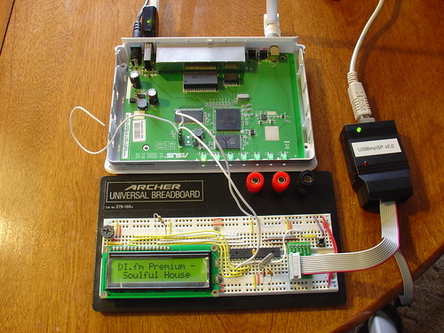
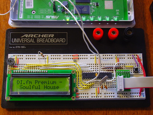
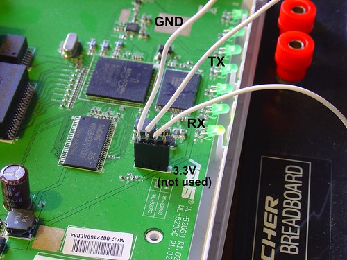
At this point we have a hacked ASUS WL-520gU wireless router running OpenWrt (Linux).   A cheap USB-audio adapter is connected to the router’s single USB port, and in part four we installed kernel drivers for Linux USB and audio support.  In part three we added a connection to the router’s internal serial port via a 4-pin header.  Wireless networking worked pretty much out of the box, and in part five we used opkg, OpenWrt’s package manager, to install mpd, the Linux music player daemon, and mpc, a command-line-based mpd client.

This gives us a compact networked device that can wirelessly connect to streaming radio stations and play 16-bit 44kHz stereo audio on a pair of headphones or amplified external speakers.  Pretty impressive, given that this device started as an inexpensive wireless router!

What’s missing?

Something big is missing from the radio.  The original concept for this radio was that it would be a standalone device.  Shell access is cool, and iPhone control is even better, but ideally we’d like to be able to see what song and station are currently playing as well as change stations without the use of another computer or mobile client.

What we need is a user interface!

Based on our requirements, the user interface needs to do two things:

  1. Display information about what’s playing from mpd
  2. Gather input from the user and tell mpd when to change stations.

A volume control will be part of our finished user interface as well, but it will be simple enough to do this in hardware when we put the radio into an enclosure.  In this part, we’ll start work on the first requirement – the display.

Note: The following steps assume you are accessing the OpenWrt shell through a telnet or ssh connection, not using the FTDI USB-serial cable.  The reasons for this will become obvious later, when we start using the router’s serial port for other purposes!

First of all, how do we get information about what’s currently playing on our radio?

Chatting with mpd:

The command-line program mpc that we installed in part five will return information about the current song if we execute it without any options:

root@OpenWrt:~# mpc
SLAY Radio: Jogeir Liljedahl - Terra Cresta
[playing] #1/5  22:36/0:00 (100%)
volume: 60%   repeat: on    random: off

Mpc obtains playlist, volume, and settings information by sending queries to the mpd server running on the router.  The mpd site includes an overview of the communications protocol and command set.  By default, mpd listens for commands on port 6600.  You can access this port remotely by using one of many client programs, or locally by opening a telnet connection to port 6600 locally (the commands are in bold for clarity):

root@OpenWrt:~# telnet localhost:6600
OK MPD 0.13.0
status
volume: 60
repeat: 1
random: 0
playlist: 14
playlistlength: 5x
fade: 0
state: play
song: 4
songid: 4
time: 2348:0
bitrate: 192
audio: 44100:16:2
OK
currentsong
file: http://relay3.slayradio.org:8000/
Name: SLAY Radio
Title: Jogeir Liljedahl - Terra Cresta
Pos: 0
Id: 0
OK

The connection will timeout in about a minute if left idle.

As you can see, there is a lot of information available, including some of the same information mpc gave us earlier.  The advantage of directly accessing mpd is that we get the stream name (the Name: line) and the artist/title (the Title: line) broken down separately instead of on one continuous line, with handy labels that will make it easy for us to parse the data later.

We can also access mpd by using the nc command, short for “network cat”.  Using nc allows us to easily pipe data from other commands to mpd and examine the results.

root@OpenWrt:~# echo "currentsong" | nc localhost 6600
file: http://relay3.slayradio.org:8000/
Name: SLAY Radio
Title: Jogeir Liljedahl - Terra Cresta
Pos: 0
Id: 0
OK

(As an aside, OpenWrt uses a program called busybox to emulate a UNIX-style shell environment – several common shell commands are included.  There is considerable documentation here, but not all commands listed are actually included in the default OpenWrt busybox installation.)

If we just want the name and title of the current song, we can use the UNIX command grep to strip out just those two lines:

root@OpenWrt:~# echo "currentsong" | nc localhost 6600 | grep -e "^Title: " -e "^Name: "

Name: SLAY Radio
Title: Jogeir Liljedahl - Terra Cresta

Talking to external devices:

Now that we have a way to get song information from mpd, we need a way to direct this information to an external display.  The router comes with a handy mechanism for doing this – the builtin serial port.  Linux makes it easy to direct the output of grep to the router’s serial port, just add a redirect to /dev/tts/0 at the end of the command (all on one line, wrapped here to fit the page):

root@OpenWrt:~# echo "currentsong" | nc localhost 6600 | grep -e "^Title: "
-e "^Name: " > /dev/tts/0
root@OpenWrt:~#

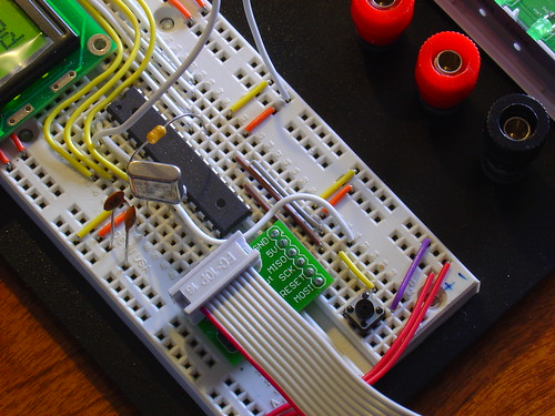
However, it turns out that the serial port’s default speed of 115200 baud is too fast for some external displays.  If we want to be able to talk to an AVR microcontroller, for example, we need to change the speed of the serial port from it’s default value of 115200 to 9600 baud.  This can be done easily with the stty command.

Note: If you downloaded and installed OpenWrt prior to December 3rd by using the files on this site, stty is most likely missing from your installation.  Unfortunately, the only way I know of to easily fix this is to completely reinstall OpenWrt, since stty is part of busybox and included in the base firmware image.  You can check if you have it by executing ‘stty’ from the command line of the router – if you get an error, you will need to reinstall.

You can change the baud rate of the serial port by executing:

root@OpenWrt:~# stty 9600 < /dev/tts/0

Connect your FTDI USB-serial cable to the router’s serial port and open a terminal program set to 9600 baud, 8N1. Execute the last mpd query again, you should see the name and title appear in your terminal window:

root@OpenWrt:~# echo "currentsong" | nc localhost 6600 | grep -e "^Title: "
-e "^Name: " > /dev/tts/0

In the terminal window:

Name: SLAY Radio
Title: Jogeir Liljedahl - Terra Cresta

Now we have a way to get information about the current song and direct it to the serial port.

We can do this is an automated way by using a shell script:

#! /bin/sh -
# display.sh - Wifi Radio LCD display routines
# 12/12/08    Jeff Keyzer    http://mightyohm.com
# This shell script queries mpd for current song information and sends
# relevant bits of it to the serial port, where an AVR-based LCD display
# is waiting.
#
# For more information, visit
# https://mightyohm.com/blog/
#
trap 'exit 1' SIGINT    # exit on ctrl-c, useful for debugging
stty 9600 < /dev/tts/0  # set serial port to 9600 baud
                        # so we can talk to the AVR
while true        # loop forever
do
 echo "currentsong" | nc localhost 6600 | grep -e "^Title: " -e "^Name: " > /dev/tts/0
 sleep 1
done

You can either copy and paste this script to a file on the router, or download it with wget:

root@OpenWrt:~# cd ~
root@OpenWrt:~# wget http://mightyohm.com/files/wifiradio/display.sh
Connecting to mightyohm.com (72.32.209.132:80)
display.sh           100% |*******************************|   668  --:--:-- ETA

Be sure to make the script executable by using chmod:

root@OpenWrt:~# chmod ugo+x display.sh

If you run the script you should see the name and title information update in the serial terminal once a second.

root@OpenWrt:~# ./display.sh

The script will loop forever – hit control-c in the router’s shell to exit.

That’s it for part six!  In part seven, we’ll add an AVR-based serial LCD display to the router – stay tuned!

Update: Part seven is now available.

Update 2: There is a new Wifi Radio Discussion Forum, hop over there to ask questions about the project or see what other people are working on!  (4/12/09)

Bluetooth Handset Hack

Bluetooth Handset Hack

Kylie recently gave me an old, broken Motorola HS820 bluetooth headset.  The headset suffered from a defective microphone that resulted in extremely low volume on outgoing audio, even though everything else worked fine.

Upon receiving it, I proceeded to rip the headset apart, interested to see what was inside.  I found a fairly simple PCB with a discrete bluetooth module in the center.  The PCB is not labeled, but given that this is an older headset (3-4 years old) most of the connections are large enough to attack with a pencil iron and solder wires to.

This headset was begging for a project.

Motorola HS-820 PCB - Back

On my last trip to Weird Stuff, I came across the beauty shown below.  The instant I saw it (and three other boxes full of others like it) I knew exactly what I was going to do with the broken headset: make it into a Bluetooth Handset instead.

Shown below is a vintage International Telephone & Telegraph telephone handset.  ITT manufactured phones in the 60s and 70s;  later they spun off that part of the business to Alcatel and then got into some trouble with the government in 2007.

Vintage ITT Telephone Handset

The handset has some heft to it and feels great to use.  It is amazing how accustomed we have become to using extremely ergonomically poor cellphones.  Just compare the shape and size of a modern cellphone to a handset like this and you can understand why it is so refreshing to pick up and use one of these.

They don’t make them like this anymore.  Unscrewing the faceplates reveals a speaker and a microphone which falls out onto the floor if you’re not careful.  I remember phones like this when I was very young but hadn’t seen one in years.

Vintage ITT Telephone Handset

Sticking the guts of the HS820 into the handset was not that difficult or time consuming.  The speaker works as-is.  It turns out the impedance of the speaker that came with the bluetooth headset is around 30 ohms, while the vintage handset speaker is 42 ohms, close enough.  The audio quality is excellent!

The original microphone on the HS820 was an electret, which is not the same as the carbon style on the handset.  Despite this, I was able to get the microphone on the handset to work by adding a 1k series resistor and wiring it to the same terminals on the headset as the original.  Without the resistor, my voice was too loud and distorted.  The value took some experimentation and I may continue to play with it, or eventually give up and install a modern electret style mic instead (but the original is just too cool).

I added a pushbutton to replace the multifunction button on the headset.  Holding down this button turns the handset on and off.  Pushing it answers calls and probably does other stuff that I haven’t played with.  The headset has volume buttons too, but the volume can be controlled via software so I didn’t wire them up to anything.

Pushbutton

I also added a charging jack where the cord originally was.  The washer is needed to fill the relatively large opening for the cord.

Charging jack

A ridiculously bright blue LED is wired in place of the status LED on the headset.  I found the LED holder in my junk box.

Bluetooth Handset Hack

This shows the connections for the pushbutton (yellow and green wires in the center) and the LED (red and black in the bottom center).  I removed the original pusbutton with my hot air rework station and soldered the new wires in place, then put a dab of hot glue on top to keep them in place.  The big blue thing in the middle is the bluetooth module.  I imagine that modern headsets do not have a discrete PCB for this.  The HS820 PCB tucks inside the center of the handset when installed and stays in place without any special mounting.

Bluetooth Handset Hack

The other side of the HS820 PCB shows the 3.7V lithium battery and the connections for the microphone (lower left), speaker (lower right) and charger (upper right).  The battery is glued to the PCB.

Bluetooth Handset Hack

I modified the Motorola charger that came with the headset by cutting off the original 3 pin plug and replacing it with a 4.7mm power connector to match the jack on the phone.  The third pin of the original connector wasn’t being used anyway.

Bluetooth Handset Charger

To charge the handset, you just plug in the charger.  The LED lights up to show that the handset is charging and goes out when it’s done.  It flashes during normal use, blinding spectators.

Charging

I’m planning to use this for Skype on my desktop computer, but I may just have to carry it around for a few days to see what other people think of it…

Update: As mentioned in the comments, these are for sale at ThinkGeek.com, search for “retro handset”.

Update 2 (11/20/09): Welcome, Make: readers!  Questions about this project?  Head over to the forums for help!