I just uploaded version 1.1 of the Arduino sketch, which fixes an issue with garbage being printed in the serial monitor between burn cycles. I also made some minor changes to try to reduce the likelihood of getting serial gibberish upon opening the monitor window, although I’m not 100% sure what is causing this. The sketch was compiled and tested with Arduino 0017.
I have verified that the shield works with the Atmel ATmega328P AVR microcontroller.
Nine close friends built Conway’s Game of Life kits from Adafruit Industries. This is my favorite kit for these kinds of workshops because it’s easy for beginners to complete in about 2 hours, and when everyone is done, you can wire all of the kits together to create one large cellular automata display. The last time I helped people build this kit was at a Make:SF workshop at the TechShop in Menlo Park.
The capture interval was 5 seconds. I used Quicktime Pro to stitch the images together at 15fps and iMovie to add titles and music (Turbo Outrun by FRP from remix.kwed.org.)
I wore my Halloween costume for most of the afternoon. What am I? Most people on the streets of San Francisco had no idea…
Safety first!
Stuart was the first to finish his kit:
Soldering the kits together to form the matrix:
Nine happy kit-builders with the 3×3 matrix they created with their finished kits:
And lastly, a video of the 3×3 matrix in action:
Three people had little to no soldering experience at the beginning of the afternoon. Everyone who came went home with a working kit. Success!
Good news! The AVR HV Rescue Shield kits are back in stock, with new, lower pricing!
The full kit, which has been reduced to $19, includes a professionally made PCB with preassembled DC-DC converter and all the parts you need to build the AVR HV Rescue Shield.
The PCB-only option is still available, which includes one unassembled PCB (DC-DC converter is not included). Pricing on the PCBs has been reduced to $6.
Back in March, I released the AVR HV Rescue Shield, my first open source hardware kit. The AVR HV Rescue Shield is a high voltage parallel mode fuse programmer for Atmel AVR microcontrollers.
Since then, I’ve sold dozens of kits around the world.
If you bought a kit, I want to hear from you! Specifically, I’d like feedback on the following items:
Was the kit easy to assemble? Are the assembly instructions clear and easy to follow?
Are you satisfied with the kit? Does it work as advertised?
Have you modified the kit or Arduino sketch in any way, such as adding support for more AVRs or programming modes?
Have you taken advantage of the Open Source Hardware model or CC-licensing to re-use this design in a new and interesting way that you’d like to share?
You can leave feedback in the comments below, or if you want to respond privately, use the contact form to contact me directly.
Based on the date of my first post, last Wednesday marked the one year anniversary of my blog.
While I pour a toast, here are a few highlights of the past year:
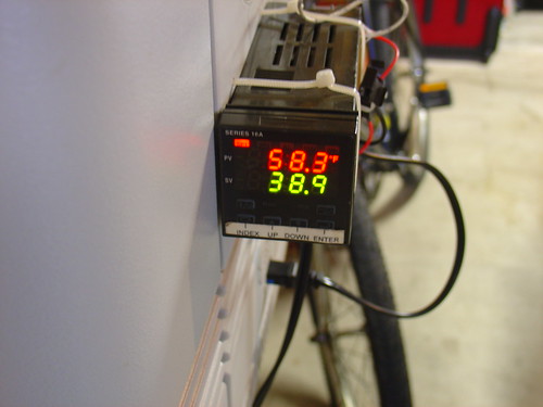
PID Controlled Solder Paste Fridge
The first project I documented on the site, my solder paste fridge was the end result of a weekend effort to turn an old beer chest into a PID-controlled Peltier cooler for storing tubes of solder paste. A year later, the cooler has a permanent home under my workbench and is still going strong, keeping its contents at a chilly 36 degrees F. Besides solder paste, I keep my POR-15 rust proofing epoxy paint and a few tubes of superglue in the fridge (they never dry out!).
Space Invaders! Making RGB video with the PIC
I needed an excuse to learn assembly language programming on the PIC, and this project fit the bill perfectly. Instead of slogging through yet another PIC tutorial I decided to “just do it” and the video above shows the result. One of my favorite projects of last year, I have plans to build more of these and make some electronic artwork for the lab.
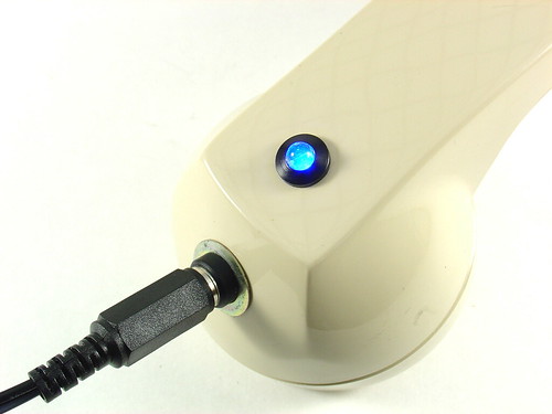
Bluetooth Handset Hack
One aging bluetooth headset plus one obsolete telephone handset equals one retro-fabulous hack that I still use today. The best part: Look for this one in Make: volume 20!
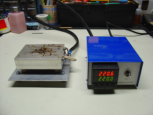
DIY PID-Controlled Soldering Hotplate
I’m a big fan of the hotplate (aka reflow skillet) method of surface mount soldering. Over the course of a few months I designed, machined, and assembled this PID-controlled soldering hotplate to help build the first few prototypes of my AVR HV Rescue Shield kit. Hacking around in the garage is always fun, but creating a new tool is one of the most rewarding things I have can think of.
Here’s a video of the hotplate in action, reflowing the step-up converter on the Rescue Shield:
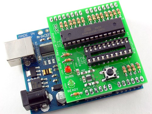
The AVR HV Rescue Shield
What started as a simple hack to save a crippled AVR microcontroller eventually became a kit that I’ve sold to AVR enthusiasts around the world. The AVR HV Rescue Shield includes a cool custom PCB, integrated 5V-12V step-up power supply, and is completely open source. I only made one batch of these, and when they’re gone, they’re gone, so head over to the AVR HV Rescue Shield product page to order one today!
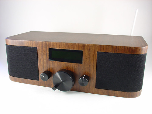
Wifi Radio Project
Certainly the most famous project on the site, my Wifi Radio project has inspired many readers to start playing with cheap wireless routers and embedded Linux. If you haven’t seen it before, the finished project sounds something like this:
I brought the Wifi Radio to the Maker Faire in San Mateo in May. Everyone loved it, including some of the Make: staff, which got me a blue ribbon for the project. Awesome!
Onward!
Well, that’s it for year one… If I missed one of your favorite posts from the past year, leave a comment! If you’re new to the blog, happy reading, you have some catching up to do. 🙂
Here’s to another fantastic year of hacks, projects, kits, tools, and resources at mightyohm.com!